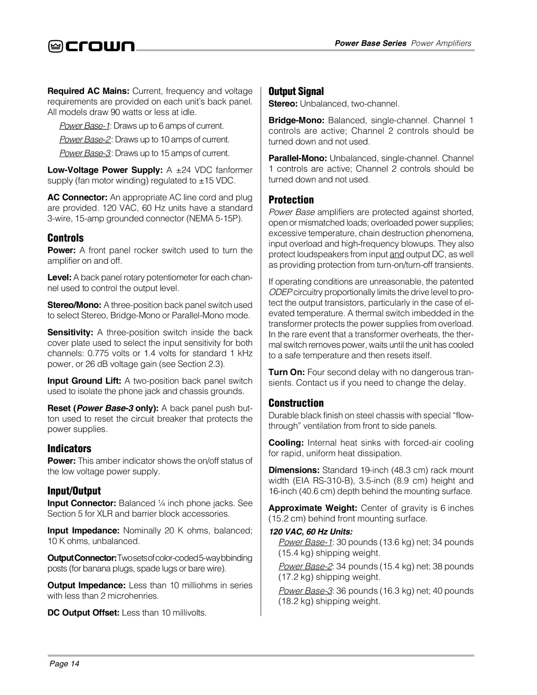
2, 3, 1 specifications
Crown 1,3,2 is a notable advancement in the field of crown-forming technology, designed to enhance efficiency and precision in various applications. Its primary features focus on a unique crown configuration that combines elements of 1, 3, and 2, allowing for versatility in production. This design enables a seamless integration of multiple functionalities, making it suitable for a wide array of industries, including beverage packaging, cosmetics, and pharmaceuticals.One of the standout features of Crown 1,3,2 is its robust construction material, which ensures durability and reliability in high-speed production environments. The materials used are resistant to corrosion and wear, making the machinery not only long-lasting but also low maintenance. This robustness translates to increased uptime and lower operational costs over time, appealing to manufacturers looking to enhance their bottom line.
In terms of technology, the Crown 1,3,2 incorporates advanced automation systems that streamline the production process. The integration of smart sensors enables real-time monitoring, providing operators with essential data to optimize performance and reduce waste. This technology allows for predictive maintenance, which further minimizes downtime by addressing potential issues before they develop into significant problems.
Another significant characteristic of the Crown 1,3,2 is its adaptability. The machine can be easily reconfigured for different production runs, accommodating varying crown sizes and shapes. This flexibility ensures that manufacturers can respond quickly to market demands without investing in additional machinery. The user-friendly interface also facilitates easy adjustments and programming, simplifying the training process for new operators.
Energy efficiency is another critical attribute of the Crown 1,3,2. The design emphasizes minimal energy consumption while maintaining high throughput rates. This focus on sustainability aligns with industry trends towards greener production methods, ensuring manufacturers can meet their environmental goals without compromising on productivity.
In summary, Crown 1,3,2 is a revolutionary solution that combines durability, advanced technology, and adaptability. Its innovative design and energy-efficient operations make it a valuable addition to any production line, enabling manufacturers to enhance their productivity while maintaining high-quality standards. Its ability to easily transition between different crown configurations further solidifies its position as a must-have tool for modern manufacturing facilities.

