CT Power Amplifiers
7 Back Panel
1 | 2 | 3 | 4 | 5 |
6 | 5 | 6 | 7 |
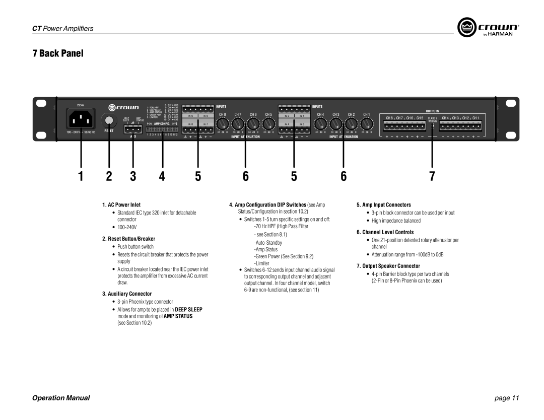
1.AC Power Inlet
•Standard IEC type 320 inlet for detachable connector
•
2.Reset Button/Breaker
•Push button switch
•Resets the circuit breaker that protects the power supply
•A circuit breaker located near the IEC power inlet protects the amplifier from excessive AC current draw.
3.Auxiliary Connector
•3-pin Phoenix type connector
•Allows for amp to be placed in DEEP SLEEP mode and monitoring of AMP STATUS (see Section 10.2)
4.Amp Configuration DIP Switches (see Amp Status/Configuration in section 10.2)
•Switches
-Green Power (See Section 9.2) -Limiter
•Switches
5.Amp Input Connectors
•
•High impedance balanced
6.Channel Level Controls
•One
•Attenuation range from
7.Output Speaker Connector
•
Operation Manual | page 11 |