CT Power Amplifiers
4 Setup
4.4 Choose Input Wire | 4.5 Choose Output Wire and |
and Connectors | Connectors |
Crown recommends using
Use
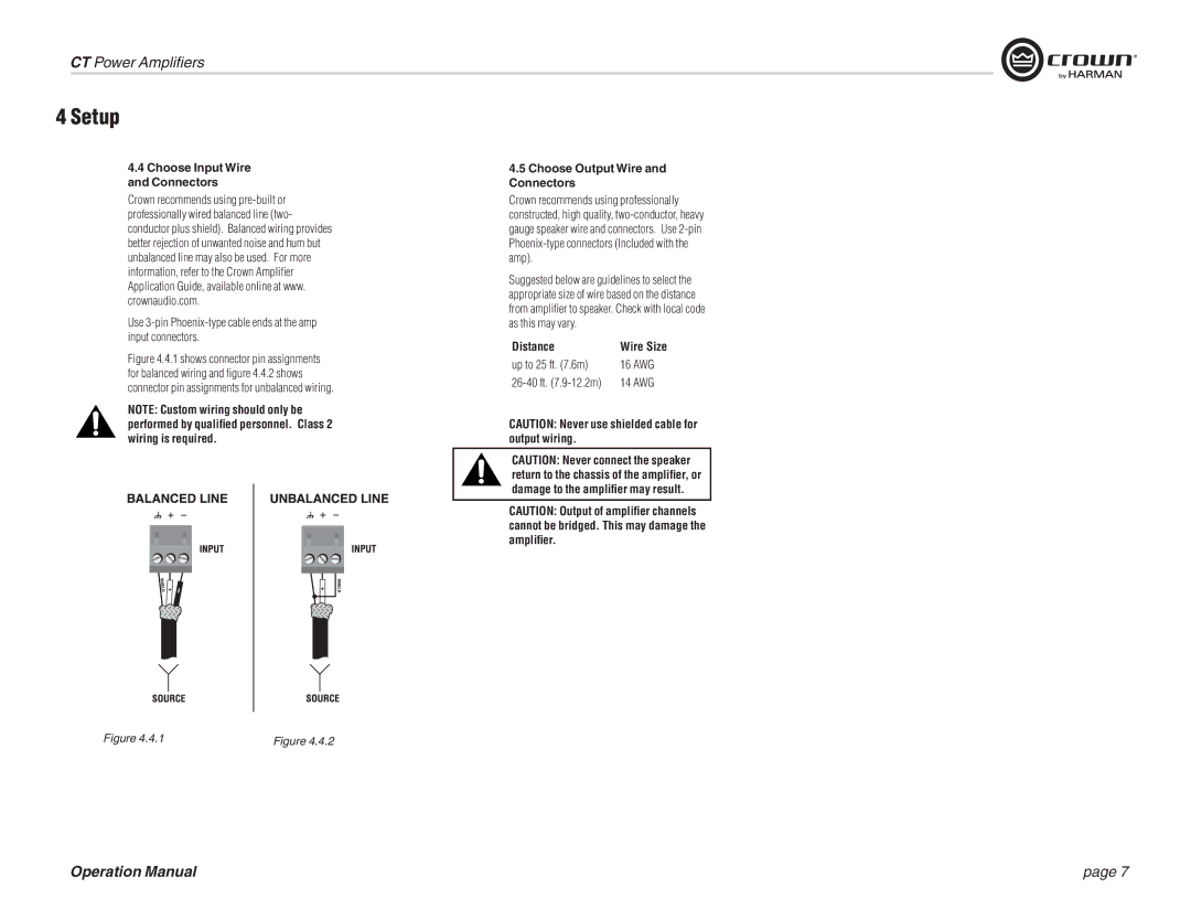
Figure 4.4.1 shows connector pin assignments for balanced wiring and figure 4.4.2 shows connector pin assignments for unbalanced wiring.
NOTE: Custom wiring should only be performed by qualified personnel. Class 2 wiring is required.
Crown recommends using professionally constructed, high quality,
Suggested below are guidelines to select the appropriate size of wire based on the distance from amplifier to speaker. Check with local code as this may vary.
Distance | Wire Size |
up to 25 ft. (7.6m) | 16 AWG |
14 AWG |
CAUTION: Never use shielded cable for output wiring.
CAUTION: Never connect the speaker return to the chassis of the amplifier, or damage to the amplifier may result.
CAUTION: Output of amplifier channels cannot be bridged. This may damage the amplifier.
Figure 4.4.1 | Figure 4.4.2 |
Operation Manual | page 7 |