CT Power Amplifiers
4 Setup
4.1 UnpackYour Amplifier | 4.2 InstallYour Amplifier | 4.3 Ensure Proper Cooling |
Please unpack and inspect your amplifier for any damage that may have occurred during transit. If damage is found, notify the transportation company immediately. Only you can initiate a claim for shipping damage. Crown will be happy to help as needed. Save the shipping carton as evidence of damage for the shipper’s inspection.
We also recommend that you save all packing materials so you will have them if you ever need to transport the unit. Never ship the unit without the factory pack.
YOU WILL NEED (not supplied):
•Input wiring cables
•Output wiring cables
•Flathead screwdriver
Rack for mounting amplifier (or a stable surface for stacking)
WARNING: Before you start to set up your amplifier, make sure you read and observe the Important Safety Instruc tions found at the beginning of this manual.
CAUTION: Before you begin, make sure your amplifier is disconnected from the power source and that all level controls (see section 7.6) are set to 0.
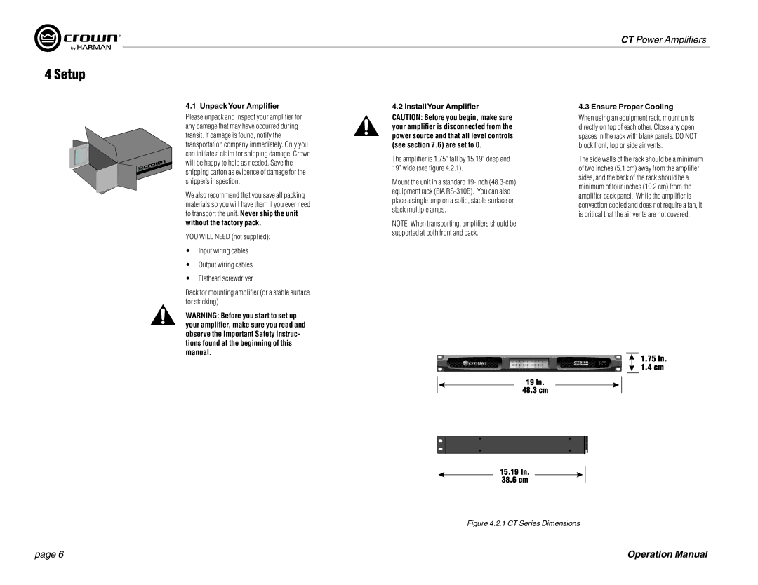
The amplifier is 1.75” tall by 15.19” deep and 19” wide (see figure 4.2.1).
Mount the unit in a standard
NOTE: When transporting, amplifiers should be supported at both front and back.
When using an equipment rack, mount units directly on top of each other. Close any open spaces in the rack with blank panels. DO NOT block front, top or side air vents.
The side walls of the rack should be a minimum of two inches (5.1 cm) away from the amplifier sides, and the back of the rack should be a minimum of four inches (10.2 cm) from the amplifier back panel. While the amplifier is convection cooled and does not require a fan, it is critical that the air vents are not covered.
Figure 4.2.1 CT Series Dimensions
page 6 | Operation Manual |