CT Power Amplifiers
6 Front Panel
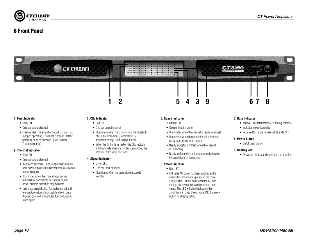
1 | 2 | 5 | 4 | 3 | 9 | 6 7 | 8 |
1.Fault Indicator
•Red LED
•One per output channel
•Flashes when the amplifier output channel has stopped operating. Usually this means that the amplifier must be serviced. (See Section 15 Troubleshooting)
2.Thermal Indicator
•Red LED
•One per output channel
•If exceeds Thermal Limits, output channels will shut down in pairs until thermal levels are within tolerant ranges.
•Illuminates when the channel approaches temperature constraints or is about to shut down. Audible distortion may be heard.
•Unit stops amplification for each channel until temperature returns to acceptable level. Once the amp cools off enough, led turns off, audio starts again.
3.Clip Indicator
•Red LED
•One per output channel
•Illuminates when the channel is at the threshold of audible distortion (See Section 15 Troubleshooting – reduce input level)
•When the limiter is turned on the Clip Indicator will illuminate when the limiter is protecting the amplifier from input overload.
4.Signal Indicator
•Green LED
•One per input channel
•Illuminates when the input signal exceeds
5.Ready Indicator
•Green LED
•One per input channel
•Illuminates when the channel is ready for signal
•Illuminates when the channel is initialized and ready to produce audio output.
•Ready indicator will flash when the channel is in standby.
•Ready Indictor will not illuminate or flash when the amplifier is in deep sleep.
6.Power Indicator
•Blue LED
•Indicates AC power has been applied and is within the safe operating range of the power supply. The LED will flash when the AC line voltage is above or below the nominal rated value. The LED will also flash when the amplifier is in Deep Sleep mode AND the power button has been pushed.
7.Data Indicator
•Yellow LED (not functional in analog version)
•Indicates network activity
•Reserved for future releases (Lite and DSP)
8.Power Button
•On/off push button
9.Cooling Vent
•Allows for air flow and cooling of the amplifier
page 10 | Operation Manual |