4 Setup
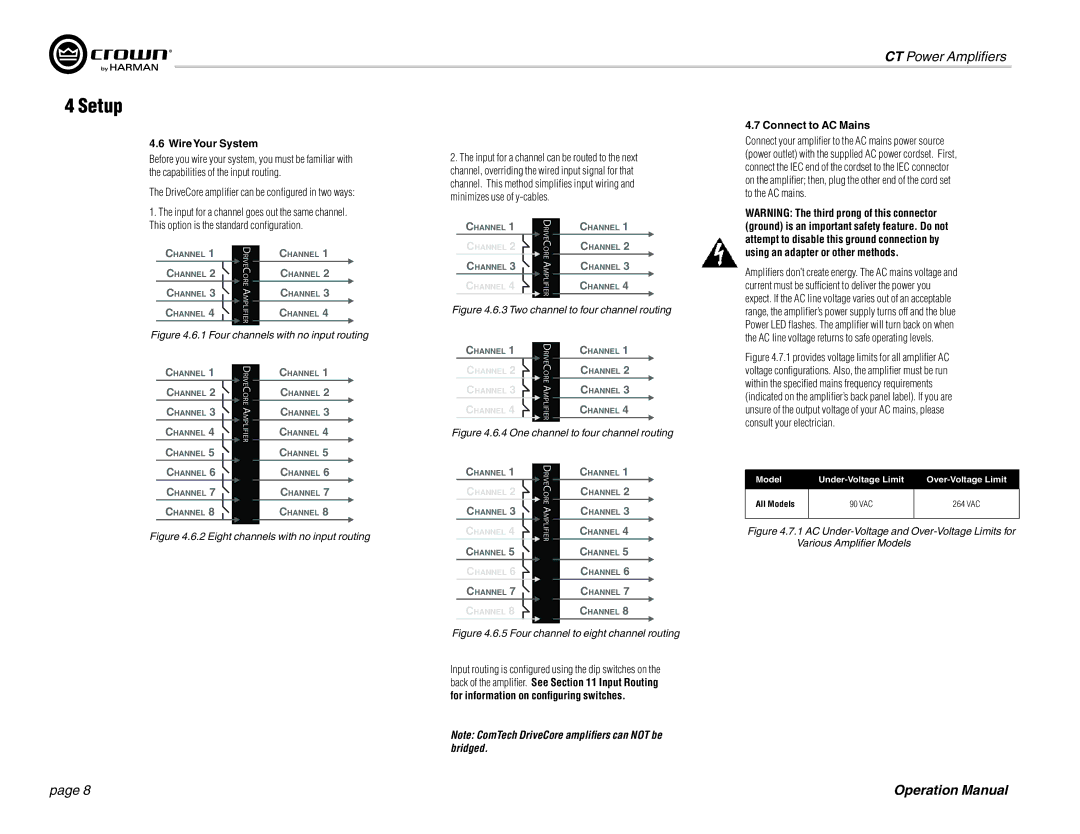
4.6 WireYour System
Before you wire your system, you must be familiar with the capabilities of the input routing.
The DriveCore amplifier can be configured in two ways:
2.The input for a channel can be routed to the next channel, overriding the wired input signal for that channel. This method simplifies input wiring and minimizes use of
CT Power Amplifiers
4.7 Connect to AC Mains
Connect your amplifier to the AC mains power source (power outlet) with the supplied AC power cordset. First, connect the IEC end of the cordset to the IEC connector on the amplifier; then, plug the other end of the cord set to the AC mains.
1.The input for a channel goes out the same channel. This option is the standard configuration.
CHANNEL 1
DRIVE
CHANNEL 1
WARNING: The third prong of this connector (ground) is an important safety feature. Do not attempt to disable this ground connection by
CHANNEL 1
CHANNEL 2
CHANNEL 3
DRIVECORE A
CHANNEL 1
CHANNEL 2
CHANNEL 3
CHANNEL 2
CHANNEL 3
CHANNEL 4
CORE AMPLIFIER
CHANNEL 2
CHANNEL 3
CHANNEL 4
using an adapter or other methods.
Amplifiers don’t create energy. The AC mains voltage and current must be sufficient to deliver the power you expect. If the AC line voltage varies out of an acceptable
CHANNEL 4
MPLIFIER
CHANNEL 4
Figure 4.6.3 Two channel to four channel routing
range, the amplifier’s power supply turns off and the blue Power LED flashes. The amplifier will turn back on when
Figure 4.6.1 Four channels with no input routing
the AC line voltage returns to safe operating levels.
CHANNEL 1
CHANNEL 2
CHANNEL 3
CHANNEL 4
CHANNEL 5
DRIVECORE AMPLIFIER
CHANNEL 1
CHANNEL 2
CHANNEL 3
CHANNEL 4
CHANNEL 5
CHANNEL 1 | DRIVE | CHANNEL 1 | |
CHANNEL 2 | CHANNEL 2 | ||
CORE | |||
|
| ||
CHANNEL 3 | AMPLIFIER | CHANNEL 3 | |
CHANNEL 4 | CHANNEL 4 | ||
| |||
|
|
|
Figure 4.6.4 One channel to four channel routing
Figure 4.7.1 provides voltage limits for all amplifier AC voltage configurations. Also, the amplifier must be run within the specified mains frequency requirements (indicated on the amplifier’s back panel label). If you are unsure of the output voltage of your AC mains, please consult your electrician.
CHANNEL 6
CHANNEL 7
CHANNEL 8
CHANNEL 6
CHANNEL 7
CHANNEL 8
CHANNEL 1
CHANNEL 2
CHANNEL 3
DRIVECORE A
CHANNEL 1
CHANNEL 2
CHANNEL 3
Model | ||
|
|
|
All Models | 90 VAC | 264 VAC |
|
|
|
Figure 4.6.2 Eight channels with no input routing
CHANNEL 4
CHANNEL 5
CHANNEL 6
CHANNEL 7
CHANNEL 8
MPLIFIER
CHANNEL 4
CHANNEL 5
CHANNEL 6
CHANNEL 7
CHANNEL 8
Figure 4.7.1 AC Under-Voltage and Over-Voltage Limits for Various Amplifier Models
page 8
Figure 4.6.5 Four channel to eight channel routing
Input routing is configured using the dip switches on the back of the amplifier. See Section 11 Input Routing for information on configuring switches.
Note: ComTech DriveCore amplifiers can NOT be bridged.
Operation Manual