Manuals
/
Crown Audio
/
Home Audio
/
Stereo Amplifier
Crown Audio
CE2000TX
operation manual
Controls, Indicators and Connectors
Models:
CE2000TX
1
15
28
28
Download
28 pages
41.11 Kb
12
13
14
15
16
17
18
19
Troubleshooting
Specification
Fault Monitoring
Wire Your System Stereo Mode
Warranty
Setup
Neutrik Speakon Connector
Startup Procedure
How to
Safety
Page 15
Image 15
CE2000TX
Power Amplifier
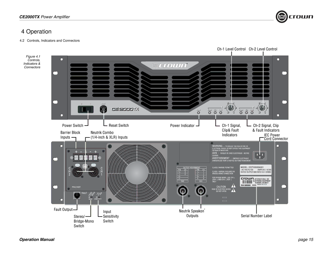
4 Operation
4.2 Controls, Indicators and Connectors
Figure 4.1
Controls,
Indicators &
Connectors
Operation Manual
page 15
Page 14
Page 16
Page 15
Image 15
Page 14
Page 16
Contents
Some models may be exported under the name Amcron
CE 2000TX
Importantes Instructions de Sécurité
Important Safety Instructions
Competent Body’s Name and Address
Safety Standard
Crown International, Inc
TCF Technical Certificate No C975CRI1.ABS
Table of Contents
Accurate, undistorted sound
How to Use This Manual
Features
Welcome
Setup
Unpack Your Amplifier Install Your Amplifier
You may also stack amps without using a cabinet
Balanced Input Connector Wiring
Choose Input Wire and Connectors
Neutrik Speakon Connector
Choose Output Wire and Con- nectors
Wire Your System Stereo Mode
How to Parallel the Inputs in Stereo Mode
See the next page for Bridge-Mono wiring
11 Typical System Wiring, Bridge Mono Mode
Bridge-Mono Mode
CE2000TX Power Amplifier
CE2000TX Power Amplifier
CE2000TX Power Amplifier
Operation
Input Sensitivity Switch
Startup Procedure
Precautions
Controls, Indicators and Connectors
Advanced Features Options
SST-4622
SST-3632
SST-4632
Location of Fault Jack
Fault Monitoring
Options Alternate Output Connectors
Optional 0.775V Input Sensitivity Setting
Tamper-Resistant Hole Plugs
Principles of Operation
Power LED is driven from the low-voltage supply
+ HI-VOLTAGE Bootstrap
Condition Power indicator is off
Troubleshooting
120 VAC, 60 Hz Units, Bridge mono mode
Specifications
Service
United States & Canada
Warranty
Worldwide Except USA & Canada
Crown Audio Factory Service Information
Top
Page
Image
Contents