CE2000TX Power Amplifier
5 Advanced Features
and Options
5.2.2 Fault Monitoring
The Fault
When using this circuit, the LED will glow whenever the amplifier is in one of four states: a channel’s heatsink has reached its temperature limit, the transformer has reached its tempera- ture limit, the amplifier has just been turned on and is in its
If you choose to design your own circuit to interface this signal to your system, note that this RJ jack is polarity sensitive. Pin 2 must be grounded, and Pin 5 must be supplied with a positive voltage pull up (positive with respect to ground). Refer to Figure 5.4 for RJ jack pin assignments. The maximum signal that can be exposed to the fault jack is 35VDC and 10 mA. Best results are obtained with 10 mA LEDs.
The mating connector for the CE 2000TX
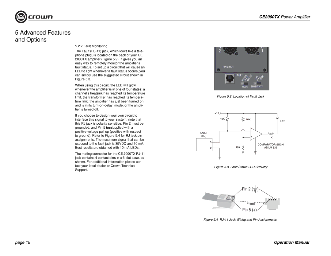
Figure 5.2 Location of Fault Jack
Figure 5.3 Fault Status LED Circuitry
Figure 5.4 RJ-11 Jack Wiring and Pin Assignments
page 18 | Operation Manual |