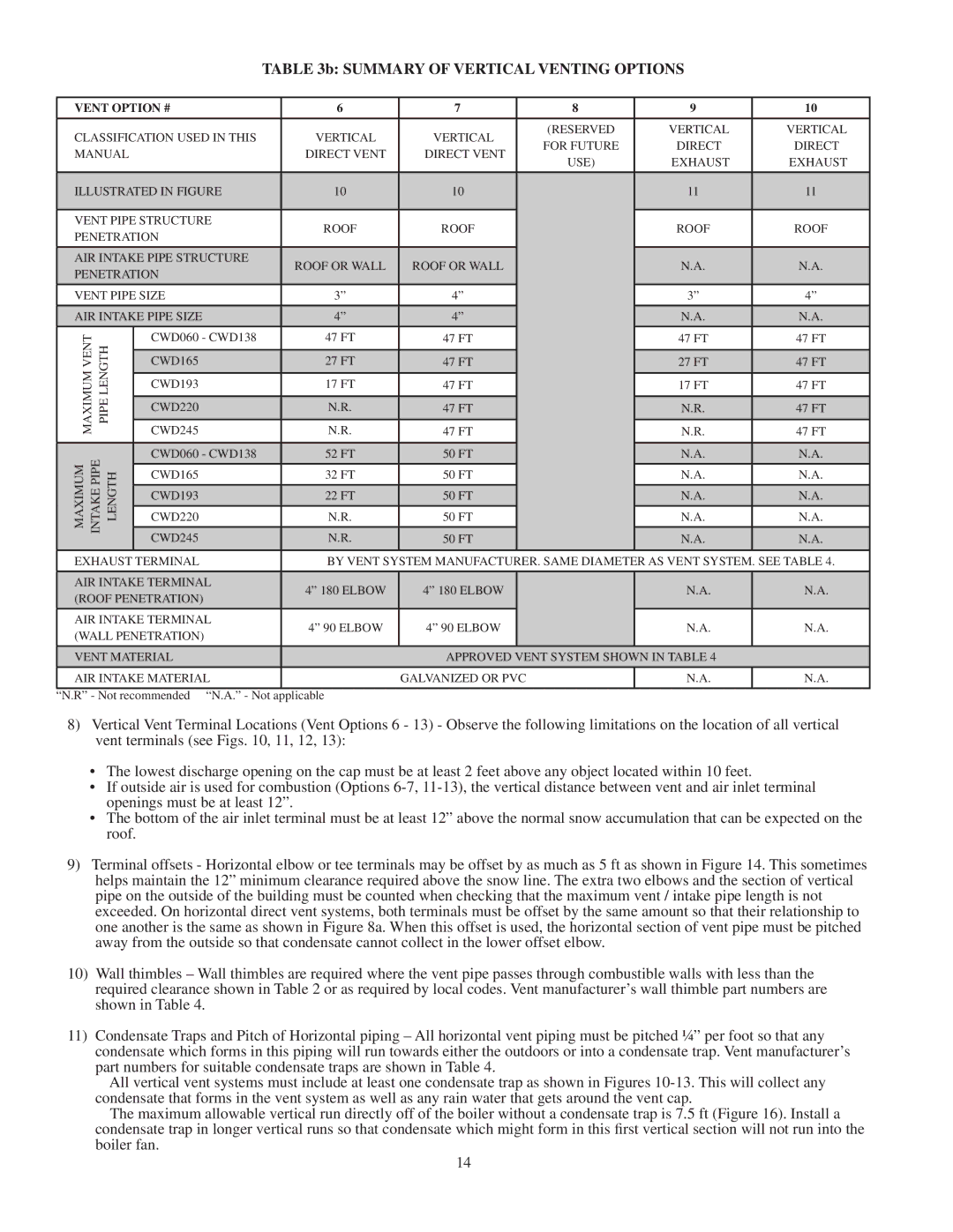
TABLE 3b: SUMMARY OF VERTICAL VENTING OPTIONS

VENT OPTION #

6

7


8

9

10


CLASSIFICATION USED IN THIS

VERTICAL

VERTICAL


(RESERVED

VERTICAL

VERTICAL


FOR FUTURE

DIRECT

DIRECT

MANUAL


DIRECT VENT

DIRECT VENT


USE)

EXHAUST

EXHAUST


ILLUSTRATED IN FIGURE

10

10


11

11


VENT PIPE STRUCTURE

ROOF

ROOF


ROOF

ROOF

PENETRATION


AIR INTAKE PIPE STRUCTURE

ROOF OR WALL

ROOF OR WALL


N.A.

N.A.

PENETRATION


VENT PIPE SIZE

3”

4”


3”

4”

AIR INTAKE PIPE SIZE

4”

4”


N.A.

N.A.

MAXIMUMVENT PIPELENGTH

CWD060 - CWD138

47 FT

47 FT


47 FT

47 FT


CWD245

N.R.

47 FT


N.R.

47 FT


CWD165

27 FT

47 FT


27 FT

47 FT


CWD193

17 FT

47 FT


17 FT

47 FT


CWD220

N.R.

47 FT


N.R.

47 FT


MAXIMUM PIPEINTAKE LENGTH

CWD060 - CWD138

52 FT

50 FT


N.A.

N.A.


CWD165

32 FT

50 FT


N.A.

N.A.


CWD193

22 FT

50 FT


N.A.

N.A.


CWD220

N.R.

50 FT


N.A.

N.A.


CWD245

N.R.

50 FT


N.A.

N.A.


EXHAUST TERMINAL

BY VENT SYSTEM MANUFACTURER. SAME DIAMETER AS VENT SYSTEM. SEE TABLE 4.

AIR INTAKE TERMINAL

4” 180 ELBOW

4” 180 ELBOW


N.A.

N.A.

(ROOF PENETRATION)


AIR INTAKE TERMINAL

4” 90 ELBOW

4” 90 ELBOW


N.A.

N.A.

(WALL PENETRATION)


VENT MATERIAL


APPROVED VENT SYSTEM SHOWN IN TABLE 4


AIR INTAKE MATERIAL


GALVANIZED OR PVC


N.A.

N.A.

“N.R” - Not recommended “N.A.” - Not applicable

8)Vertical Vent Terminal Locations (Vent Options 6 - 13) - Observe the following limitations on the location of all vertical vent terminals (see Figs. 10, 11, 12, 13):

The lowest discharge opening on the cap must be at least 2 feet above any object located within 10 feet.

If outside air is used for combustion (Options 6-7, 11-13), the vertical distance between vent and air inlet terminal openings must be at least 12”.

The bottom of the air inlet terminal must be at least 12” above the normal snow accumulation that can be expected on the roof.

9)Terminal offsets - Horizontal elbow or tee terminals may be offset by as much as 5 ft as shown in Figure 14. This sometimes helps maintain the 12” minimum clearance required above the snow line. The extra two elbows and the section of vertical pipe on the outside of the building must be counted when checking that the maximum vent / intake pipe length is not exceeded. On horizontal direct vent systems, both terminals must be offset by the same amount so that their relationship to one another is the same as shown in Figure 8a. When this offset is used, the horizontal section of vent pipe must be pitched away from the outside so that condensate cannot collect in the lower offset elbow.

10)Wall thimbles – Wall thimbles are required where the vent pipe passes through combustible walls with less than the required clearance shown in Table 2 or as required by local codes. Vent manufacturer’s wall thimble part numbers are shown in Table 4.

11)Condensate Traps and Pitch of Horizontal piping – All horizontal vent piping must be pitched ¼” per foot so that any condensate which forms in this piping will run towards either the outdoors or into a condensate trap. Vent manufacturer’s part numbers for suitable condensate traps are shown in Table 4.

All vertical vent systems must include at least one condensate trap as shown in Figures 10-13. This will collect any condensate that forms in the vent system as well as any rain water that gets around the vent cap.

The maximum allowable vertical run directly off of the boiler without a condensate trap is 7.5 ft (Figure 16). Install a condensate trap in longer vertical runs so that condensate which might form in this first vertical section will not run into the

boiler fan.

14

Page 16
Image 16
Crown Boiler CWD083, CWD220, CWD060, CWD165, CWD138, CWD193, CWD245, CWD110 Summary of Vertical Venting Options

CWD193, CWD165, CWD245, CWD220, CWD110 specifications

Crown Boiler Company is well-known for its commitment to quality and performance in the heating industry. Among its extensive range of products, the Crown Boiler CWD series stands out for its reliability and efficiency. This series includes models CWD060, CWD083, CWD110, CWD138, and CWD220, each designed to meet diverse heating needs in residential and commercial applications.

One of the main features of the CWD series is its durable construction. Made with high-quality materials, these boilers are built to withstand the test of time. The cast iron heat exchanger delivers exceptional heat retention and efficiency, ensuring optimal performance even in demanding conditions. Additionally, the CWD models are equipped with a reliable standing pilot ignition system, which enhances user safety and operational reliability.

Another important characteristic of the Crown CWD series is its versatility in fuel options. These boilers can operate on either natural gas or propane, providing flexibility to homeowners and businesses depending on their preferred energy source. The ability to easily switch fuels makes these units adaptable to various heating applications, maximizing convenience for users.

Efficiency is a cornerstone of the Crown Boiler CWD series. With an AFUE rating of up to 85%, these boilers deliver substantial cost savings over the heating season. Their efficient operation not only lowers energy bills but also contributes to a reduced environmental impact, which is increasingly important in today’s energy-conscious world.

Crown’s innovative design features also include a low water cut-off and a built-in draft hood. The low water cut-off ensures safe operation by preventing the boiler from running dry, while the draft hood allows for optimal venting capabilities, minimizing the risk of dangerous flue gas build-up.

Maintenance is straightforward with the CWD series, thanks to its easy-access design. Routine service and inspections can be performed with minimal disruption, ensuring that the units maintain peak performance over their lifespan.

The Crown Boiler CWD060, CWD083, CWD110, CWD138, and CWD220 models exemplify the brand’s dedication to delivering high-quality heating solutions. With their impressive efficiency ratings, durable construction, versatile fuel options, and user-friendly features, these boilers represent a smart investment for anyone looking to enhance heating reliability and comfort in their space.