2
4
13
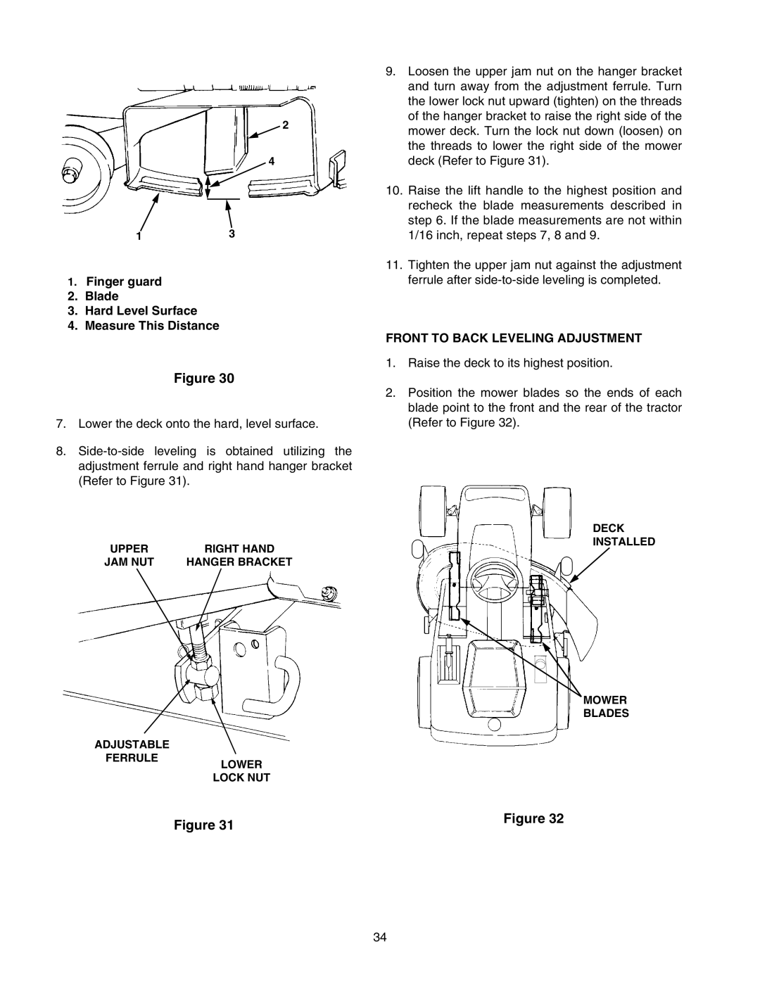
1.Finger guard
2.Blade
3.Hard Level Surface
4.Measure This Distance
Figure 30
7.Lower the deck onto the hard, level surface.
8.
UPPER | RIGHT HAND |
JAM NUT | HANGER BRACKET |
ADJUSTABLE
FERRULE
LOWER
LOCK NUT
Figure 31
9.Loosen the upper jam nut on the hanger bracket and turn away from the adjustment ferrule. Turn the lower lock nut upward (tighten) on the threads of the hanger bracket to raise the right side of the mower deck. Turn the lock nut down (loosen) on the threads to lower the right side of the mower deck (Refer to Figure 31).
10.Raise the lift handle to the highest position and recheck the blade measurements described in step 6. If the blade measurements are not within 1/16 inch, repeat steps 7, 8 and 9.
11.Tighten the upper jam nut against the adjustment ferrule after
FRONT TO BACK LEVELING ADJUSTMENT
1.Raise the deck to its highest position.
2.Position the mower blades so the ends of each blade point to the front and the rear of the tractor (Refer to Figure 32).
DECK
INSTALLED
MOWER
BLADES
Figure 32
34