USING THE THREE POINT HITCH
WARNING: Always disengage the PTO, stop the engine, and set the parking brake before dismounting the tractor to connect, disconnect, or adjust three point hitch mounted implements. Never stand between the rear wheels and the implement when attaching and adjusting the implement.
Use the
Top Link
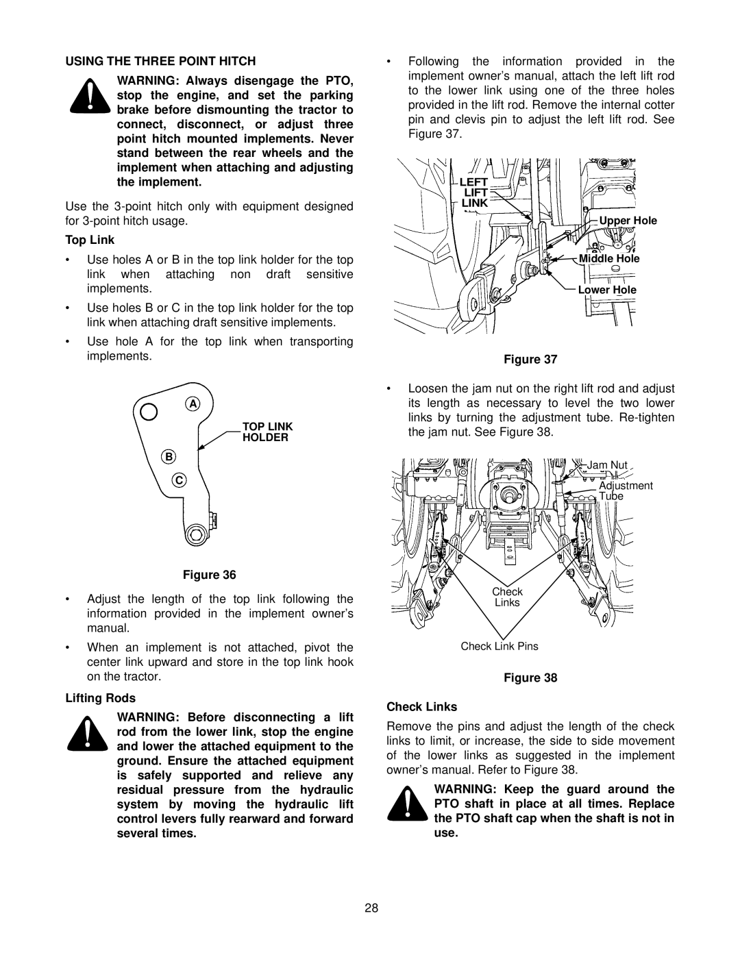
•Use holes A or B in the top link holder for the top link when attaching non draft sensitive implements.
•Use holes B or C in the top link holder for the top link when attaching draft sensitive implements.
•Use hole A for the top link when transporting implements.
A
TOP LINK
HOLDER
B
C
Figure 36
•Adjust the length of the top link following the information provided in the implement owner’s manual.
•When an implement is not attached, pivot the center link upward and store in the top link hook on the tractor.
Lifting Rods
WARNING: Before disconnecting a lift rod from the lower link, stop the engine and lower the attached equipment to the ground. Ensure the attached equipment is safely supported and relieve any residual pressure from the hydraulic system by moving the hydraulic lift control levers fully rearward and forward several times.
•Following the information provided in the implement owner’s manual, attach the left lift rod to the lower link using one of the three holes provided in the lift rod. Remove the internal cotter pin and clevis pin to adjust the left lift rod. See Figure 37.
LEFT
LIFT
LINK
![]() Upper Hole
Upper Hole
![]()
![]() Middle Hole
Middle Hole
![]()
![]() Lower Hole
Lower Hole
Figure 37
•Loosen the jam nut on the right lift rod and adjust its length as necessary to level the two lower links by turning the adjustment tube.
![]()
![]() Jam Nut
Jam Nut
Adjustment
Tube
Check
Links
Check Link Pins
Figure 38
Check Links
Remove the pins and adjust the length of the check links to limit, or increase, the side to side movement of the lower links as suggested in the implement owner’s manual. Refer to Figure 38.
WARNING: Keep the guard around the PTO shaft in place at all times. Replace the PTO shaft cap when the shaft is not in use.
28
