Setting the Gauge Wheels
Select the height position of the cutting deck by placing the deck lift lever in any of the six different cutting height notches on the right fender.
Adjust the deck wheels so that they are between
WARNING: Keep hands and feet away from the discharge opening of the cutting deck.
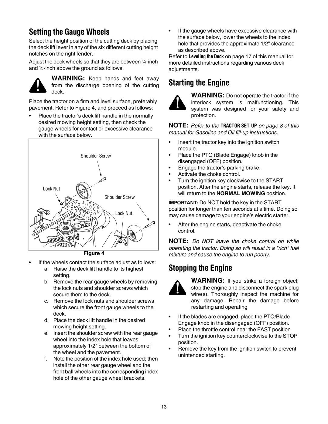
Place the tractor on a firm and level surface, preferably pavement. Refer to Figure 4, and proceed as follows:
•Place the tractor’s deck lift handle in the normally desired mowing height setting, then check the gauge wheels for contact or excessive clearance with the surface below.
Shoulder Screw |
Lock Nut |
Shoulder Screw |
Lock Nut |
Figure 4
•If the wheels contact the surface adjust as follows:
a.Raise the deck lift handle to its highest setting.
b.Remove the rear gauge wheels by removing the lock nuts and shoulder screws which secure them to the deck.
c.Remove the lock nuts and shoulder screws which secure the front gauge wheels to the deck.
d.Place the deck lift handle in the desired mowing height setting.
e.Insert the shoulder screw with the rear gauge wheel into the index hole that leaves approximately 1/2" between the bottom of the wheel and the pavement.
f.Note the position of the index hole used; then install the other rear gauge wheel and the front ball wheels into the corresponding index hole of the other gauge wheel brackets.
•If the gauge wheels have excessive clearance with the surface below, lower the wheels to the index
hole that provides the approximate 1/2" clearance as described above.
Refer to Leveling the Deck on page 17 of this manual for more detailed instructions regarding various deck adjustments.
Starting the Engine
WARNING: Do not operate the tractor if the interlock system is malfunctioning. This system was designed for your safety and protection.
NOTE: Refer to the TRACTOR
•Insert the tractor key into the ignition switch module.
•Place the PTO (Blade Engage) knob in the disengaged (OFF) position.
•Engage the tractor’s parking brake.
•Activate the choke control.
•Turn the ignition key clockwise to the START position. After the engine starts, release the key. It will return to the NORMAL MOWING position.
IMPORTANT: Do NOT hold the key in the START position for longer than ten seconds at a time. Doing so may cause damage to your engine’s electric starter.
•After the engine starts, deactivate the choke control.
NOTE: Do NOT leave the choke control on while operating the tractor. Doing so will result in a "rich" fuel mixture and cause the engine to run poorly.
Stopping the Engine
WARNING: If you strike a foreign object, stop the engine and disconnect the spark plug wire(s). Thoroughly inspect the machine for any damage. Repair the damage before restarting and operating
•If the blades are engaged, place the PTO/Blade Engage knob in the disengaged (OFF) position.
•Place the throttle control near the FAST position
•Turn the ignition key counterclockwise to the STOP position.
•Remove the key from the ignition switch to prevent unintended starting.
13