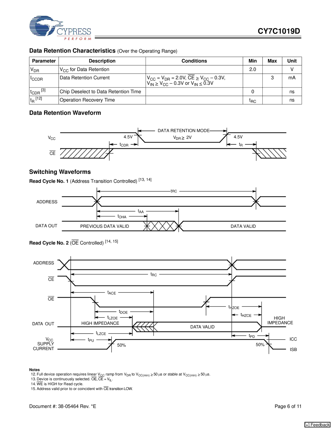
CY7C1019D specifications
The Cypress CY7C1019D is a high-performance static random-access memory (SRAM) chip designed for various applications requiring fast and reliable memory solutions. This RAM chip is particularly noted for its high-speed performance, low power consumption, and versatility, making it suitable for a wide range of electronic devices and systems.One of the main features of the CY7C1019D is its fast access time, which typically ranges from 10 ns to 15 ns. This rapid access time allows for efficient data processing and fast response times in applications such as telecommunications, networking, and consumer electronics. The chip operates at standard voltages of 2.7V to 3.6V, ensuring compatibility with modern low-voltage systems while also reducing power consumption.
Another noteworthy characteristic of the CY7C1019D is its density of 1 Megabit, organized in a 128K x 8 architecture. This configuration provides ample memory space for various data storage needs, whether in embedded systems, automotive applications, or high-speed buffering. The SRAM's structure allows for simultaneous read and write operations, enhancing overall system performance.
The CY7C1019D employs advanced CMOS technology, which contributes to its low power operation. This feature is crucial for battery-powered devices and applications where energy efficiency is a priority. The chip supports a range of operating temperatures, making it suitable for both consumer and industrial applications.
Moreover, the CY7C1019D includes various useful features such as a fast burst mode for high-speed data transfer, and it supports asynchronous data rates, enhancing its adaptability across different platforms. Its simple interface allows for easy integration into existing system architectures.
The package options for the CY7C1019D include both 32-pin and 44-pin flat packages, making it accessible for different PCB layouts and design requirements. This flexibility further contributes to its wide usage in various industries, including automotive, telecommunications, and industrial control systems.
In conclusion, the Cypress CY7C1019D SRAM chip stands out as a reliable, high-speed memory component, ideal for applications demanding quick access and efficient data management. Its combination of speed, low power consumption, and versatility makes it a preferred choice for designers looking to enhance system performance and reliability.