CY7C1324H


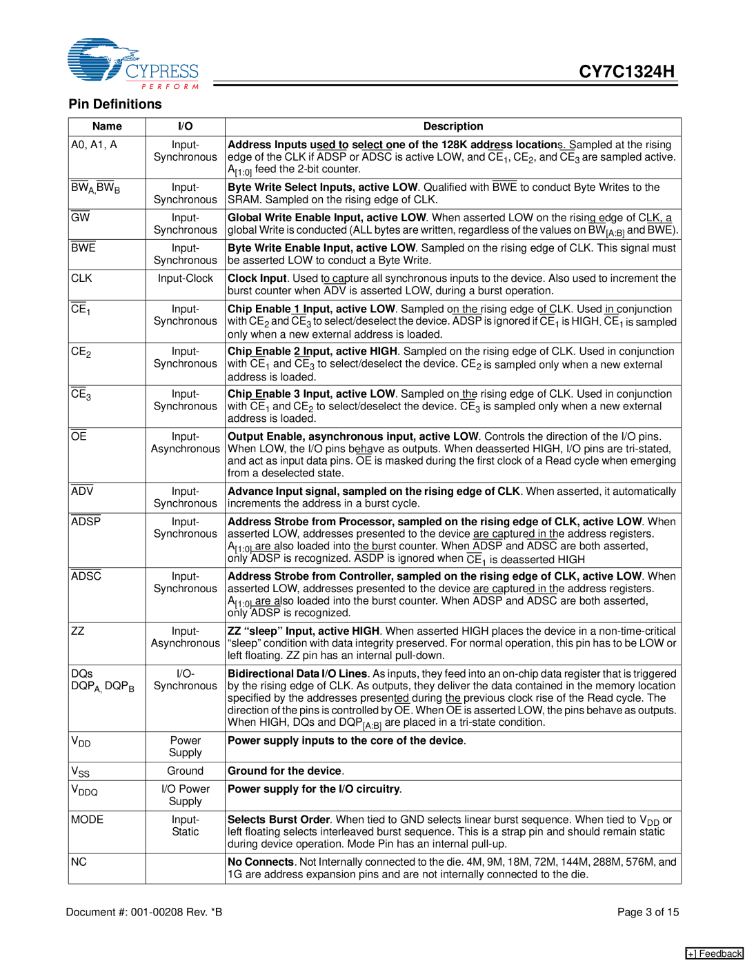
Pin Definitions


Name

I/O


Description


A0, A1, A

Input-

Address Inputs used to select one of the 128K address locations. Sampled at the rising


Synchronous

edge of the CLK if ADSP or ADSC is active LOW, and CE1, CE2, and

CE

3 are sampled active.


A[1:0] feed the 2-bit counter.


A,


B

Input-

Byte Write Select Inputs, active LOW. Qualified with


to conduct Byte Writes to the


BW

BW

BWE


Synchronous

SRAM. Sampled on the rising edge of CLK.


Input-

Global Write Enable Input, active LOW. When asserted LOW on the rising edge of CLK, a


GW


Synchronous

global Write is conducted (ALL bytes are written, regardless of the values on BW[A:B] and BWE).


Input-

Byte Write Enable Input, active LOW. Sampled on the rising edge of CLK. This signal must


BWE


Synchronous

be asserted LOW to conduct a Byte Write.


CLK

Input-Clock

Clock Input. Used to capture all synchronous inputs to the device. Also used to increment the


burst counter when ADV is asserted LOW, during a burst operation.


1


Input-

Chip Enable

1

Input, active LOW. Sampled on the rising edge of CLK. Used

in

conjunction


CE


Synchronous

with CE2 and CE3 to select/deselect the device. ADSP is ignored if CE1 is HIGH. CE1 is sampled


only when a new external address is loaded.


CE2

Input-

Chip Enable 2 Input, active HIGH. Sampled on the rising edge of CLK. Used in conjunction


Synchronous

with CE1 and CE3 to select/deselect the device. CE2 is sampled only when a new external


address is loaded.


3


Input-

Chip Enable 3 Input, active LOW. Sampled on

the

rising edge of CLK. Used in conjunction


CE


Synchronous

with CE1 and CE2 to select/deselect the device. CE3 is sampled only when a new external


address is loaded.


Input-

Output Enable, asynchronous input, active LOW. Controls the direction of the I/O pins.


OE


Asynchronous

When LOW, the I/O pins behave as outputs. When deasserted HIGH, I/O pins are tri-stated,


and act as input data pins. OE is masked during the first clock of a Read cycle when emerging


from a deselected state.


Input-

Advance Input signal, sampled on the rising edge of CLK. When asserted, it automatically


ADV


Synchronous

increments the address in a burst cycle.


Input-

Address Strobe from Processor, sampled on the rising edge of CLK, active LOW. When


ADSP


Synchronous

asserted LOW, addresses presented to the device are captured in the address registers.


A[1:0]

are also loaded into the burst counter. When ADSP and ADSC are both asserted,


only ADSP is recognized. ASDP is ignored when CE1 is deasserted HIGH


Input-

Address Strobe from Controller, sampled on the rising edge of CLK, active LOW. When


ADSC


Synchronous

asserted LOW, addresses presented to the device are captured in the address registers.


A[1:0]

are also loaded into the burst counter. When ADSP and ADSC are both asserted,


only ADSP is recognized.


ZZ

Input-

ZZ “sleep” Input, active HIGH. When asserted HIGH places the device in a non-time-critical


Asynchronous

“sleep” condition with data integrity preserved. For normal operation, this pin has to be LOW or


left floating. ZZ pin has an internal pull-down.


DQs

I/O-

Bidirectional Data I/O Lines. As inputs, they feed into an on-chip data register that is triggered


DQPA, DQPB

Synchronous

by the rising edge of CLK. As outputs, they deliver the data contained in the memory location


specified by the addresses presented during the previous clock rise of the Read cycle. The


direction of the pins is controlled by OE. When OE is asserted LOW, the pins behave as outputs.


When HIGH, DQs and DQP[A:B] are placed in a tri-state condition.


VDD

Power

Power supply inputs to the core of the device.


Supply


VSS

Ground

Ground for the device.


VDDQ

I/O Power

Power supply for the I/O circuitry.


Supply


MODE

Input-

Selects Burst Order. When tied to GND selects linear burst sequence. When tied to VDD or


Static

left floating selects interleaved burst sequence. This is a strap pin and should remain static


during device operation. Mode Pin has an internal pull-up.


NC


No Connects. Not Internally connected to the die. 4M, 9M, 18M, 72M, 144M, 288M, 576M, and


1G are address expansion pins and are not internally connected to the die.

Document #: 001-00208 Rev. *B


Page 3 of 15

[+] Feedback

Page 3
Image 3
Cypress CY7C1324H manual Pin Definitions

CY7C1324H specifications

The Cypress CY7C1324H is a high-performance SRAM (Static Random Access Memory) device that plays a crucial role in various applications requiring fast and efficient data access. This device is part of the CY7C family of SRAM products and stands out for its advanced features, robust performance metrics, and versatility in operation.

One of the most notable features of the CY7C1324H is its 32 megabit (4M x 8) memory capacity, which allows for significant data storage and retrieval capabilities. This memory is organized as a 4M word by 8 bits, making it suitable for a wide range of applications, from automotive to telecommunications and industrial control systems.

The CY7C1324H operates at a speed of 20 nanoseconds, making it an ideal choice for systems that require rapid read and write cycles. The device supports both asynchronous read and write operations, allowing for flexible interfacing with various microcontrollers and digital signal processors. This speed enhances overall system performance, especially when handling time-critical data.

In terms of technologies, the CY7C1324H employs high-speed CMOS (Complementary Metal-Oxide-Semiconductor) technology, which contributes to its low power consumption and high reliability. The device operates at a voltage range of 2.7V to 3.6V, making it suitable for battery-powered applications where energy efficiency is paramount. The integration of advanced CMOS technology also facilitates a higher degree of integration, enabling more compact designs in electronic circuits.

The device features a simple and straightforward interface, with a single enable (E) control pin that allows for easy access to memory contents. Additionally, the CY7C1324H supports both byte-wide and word-wide data accesses, making it highly adaptable for various application requirements.

Another important characteristic of the CY7C1324H is its low pin count, consisting of only 32 pins, which aids in minimizing board space and simplifying design layouts. The packaging comes in a 44-lead Thin Quad Flat Pack (TQFP), further optimizing space usage in compact electronic designs.

In summary, the Cypress CY7C1324H is a versatile, high-speed SRAM solution that offers a combination of large memory capacity, rapid access times, and low power operation. Its robust features make it an excellent choice for a broad spectrum of electronic applications, paving the way for enhanced performance and efficiency in modern electronic systems.