CY7C1399B

Pin Configuration

TSOP

Top View

OE A1

A2

A3

A4

WE

VCC

A5

A6

A7

A8

A9

A10

A11

22

21


A0


23

20


CE


24

19


I/O7


25

18


I/O6


26

17


I/O5


27

16


I/O4


28

15


I/O3


1

14


GND


2

13


I/O2


3

12


I/O1


4

11


I/O0


5

10


A14


6

9


A13


7

8


A12


Maximum Ratings

(Above which the useful life may be impaired. For user guide- lines, not tested.)

Storage Temperature

–65°C to +150° C

Ambient Temperature with

–55°C to +125° C

Power Applied

Supply Voltage on VCC to Relative GND[1] .... –0.5V to +4.6V

DC Voltage Applied to Outputs

in High Z State[1]

–0.5V to VCC + 0.5V

DC Input Voltage[1]

–0.5V to VCC + 0.5V

Electrical Characteristics Over the Operating Range[1]

Output Current into Outputs (LOW)

............................. 20 mA

Static Discharge Voltage

>2001V

(per MIL-STD-883, Method 3015)


Latch-Up Current

>200 mA

Operating Range


Ambient


Range

Temperature

VCC

Commercial

0° C to +70° C

3.3V ± 300 mV


Industrial

–40°C to +85° C

3.3V ± 300 mV


7C1399B-10

7C1399B-12


Parameter

Description

Test Conditions


Min.

Max.

Min.

Max.

Unit


VOH

Output HIGH Voltage

VCC = Min., IOH = –2.0 mA


2.4


2.4


V

VOL

Output LOW Voltage

VCC = Min., IOL = 4.0 mA


0.4


0.4

V

VIH

Input HIGH Voltage


2.2

VCC

2.2

VCC

V


+0.3V


+0.3V


VIL

Input LOW Voltage


–0.3

0.8

–0.3

0.8

V

IIX

Input Load Current


–1

+1

–1

+1

A

IOZ

Output Leakage

GND VI VCC,


–5

+5

–5

+5

A


Current

Output Disabled


IOS

Output Short

VCC = Max., VOUT = GND


–300


–300

mA


Circuit Current[2]


ICC

VCC Operating

VCC = Max., IOUT = 0 mA,


60


55

mA


Supply Current

f = fMAX = 1/tRC


ISB1

Automatic CE Power-Down

Max. VCC,

CE

VIH,


5


5

mA


Current — TTL Inputs

VIN VIH, or VIN VIL,f = fMAX


L


4


4

mA


ISB2

Automatic CE Power-Down

Max. VCC,


VCC–0.3V,VINVCC


500


500

A

CE


Current — CMOS Inputs[3]

– 0.3V, or V

0.3V,


L


50


50

A


IN


WEVCC–0.3V or WE 0.3V,f = fMAX


Notes:


1.Minimum voltage is equal to – 2.0V for pulse durations of less than 20 ns.

2.Not more than one output should be shorted at one time. Duration of the short circuit should not exceed 30 seconds.

3.Device draws low standby current regardless of switching on the addresses.

Document #: 38-05071 Rev. *A

Page 2 of 10

Page 2
Image 2
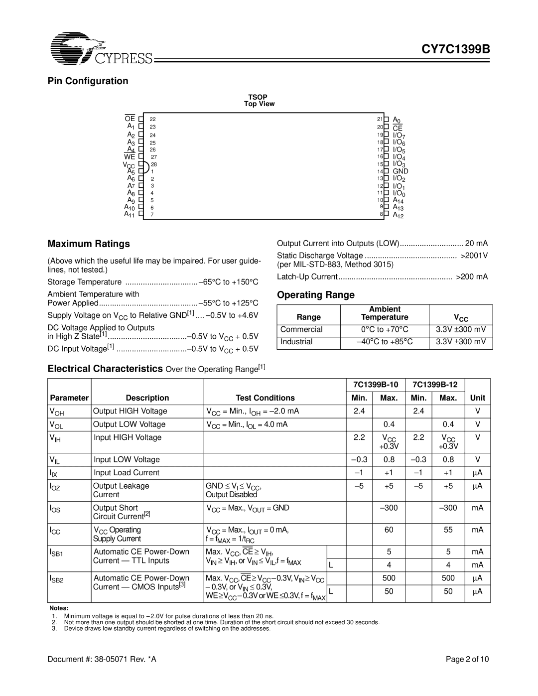
Cypress CY7C1399B manual Pin Configuration, Maximum Ratings, Electrical Characteristics Over the Operating Range1

CY7C1399B specifications

The Cypress CY7C1399B is a high-performance static random-access memory (SRAM) device that belongs to the family of asynchronous CMOS SRAMs. It is designed to deliver superior speed and efficiency, making it ideal for a multitude of applications in various fields, including telecommunications, automotive, and consumer electronics.

One of the key features of the CY7C1399B is its high-speed operation, capable of achieving access times as low as 12 nanoseconds. This allows for rapid data retrieval, which is crucial in applications requiring fast data processing and real-time performance. Moreover, it operates with a single supply voltage of 2.0V to 3.6V, providing flexibility for power-sensitive designs.

The chip comes with a capacity of 16 megabits, which enables it to store substantial amounts of data. Furthermore, it features a burst mode operation that allows for efficient access to multiple consecutive data locations. This capability makes it particularly useful in applications such as video processing, where quick data retrieval is essential.

Another prominent characteristic of the CY7C1399B is its low power consumption. The device boasts both active and standby power modes, which help minimize energy usage, making it suitable for battery-operated devices. This is increasingly becoming a vital factor for consumer electronics, where energy efficiency is a priority.

In terms of interface, the CY7C1399B uses a conventional parallel interface, compatible with a variety of microcontrollers and processors. The device also supports an asynchronous read and write operation, which simplifies integration into existing systems.

The chip is built using advanced 0.18-micron CMOS technology, which not only enhances its performance but also contributes to its reliability and durability. This technology allows the CY7C1399B to achieve high integration density, resulting in a smaller footprint on printed circuit boards (PCBs).

With a combination of high-speed operational characteristics, low power consumption, and substantial data capacity, the Cypress CY7C1399B stands out as an excellent choice for designers seeking efficient memory solutions that can support the demands of modern electronic systems.