CY7C1399B

Switching Characteristics Over the Operating Range[5]


1399B–10

1399B–12


Parameter


Description

Min.

Max.

Min.

Max.

Unit


READ CYCLE


tRC


Read Cycle Time

10


12


ns

tAA


Address to Data Valid


10


12

ns

tOHA


Data Hold from Address Change

3


3


ns

tACE


LOW to Data Valid


10


12

ns


CE


tDOE


LOW to Data Valid


5


5

ns


OE


tLZOE


LOW to Low Z[6]

0


0


ns


OE


tHZOE


HIGH to High Z[6, 7]


5


5

ns


OE


tLZCE


LOW to Low Z[6]

3


3


ns


CE


tHZCE


HIGH to High Z[6, 7]


5


6

ns


CE


tPU


LOW to Power-Up

0


0


ns


CE


tPD


HIGH to Power-Down


10


12

ns


CE


WRITE CYCLE[8, 9]


tWC


Write Cycle Time

10


12


ns

tSCE


LOW to Write End

8


8


ns


CE


tAW


Address Set-Up to Write End

7


8


ns

tHA


Address Hold from Write End

0


0


ns

tSA


Address Set-Up to Write Start

0


0


ns

tPWE


Pulse Width

7


8


ns


WE


tSD


Data Set-Up to Write End

5


7


ns

tHD


Data Hold from Write End

0


0


ns

tHZWE


LOW to High Z[8]


7


7

ns


WE


tLZWE


HIGH to Low Z[6]

3


3


ns


WE


Notes:

5.Test conditions assume signal transition time of 3 ns or less, timing reference levels of 1.5V, input pulse levels of 0 to 3.0V, and output loading of the specified IOL/IOH and capacitance CL = 30 pF.

6.At any given temperature and voltage condition, tHZCE is less than tLZCE, tHZOE is less than tLZOE, and tHZWE is less than tLZWE for any given device.

7.tHZOE, tHZCE, tHZWE are specified with CL = 5 pF as in AC Test Loads. Transition is measured ±500 mV from steady state voltage.

8.The internal write time of the memory is defined by the overlap of CE LOW and WE LOW. Both signals must be LOW to initiate a write and either signal can terminate a write by going HIGH. The data input set-up and hold timing should be referenced to the rising edge of the signal that terminates the write.

9.The minimum write cycle time for write cycle #3 (WE controlled, OE LOW) is the sum of tHZWE and tSD.

Document #: 38-05071 Rev. *A

Page 4 of 10

Page 4
Image 4
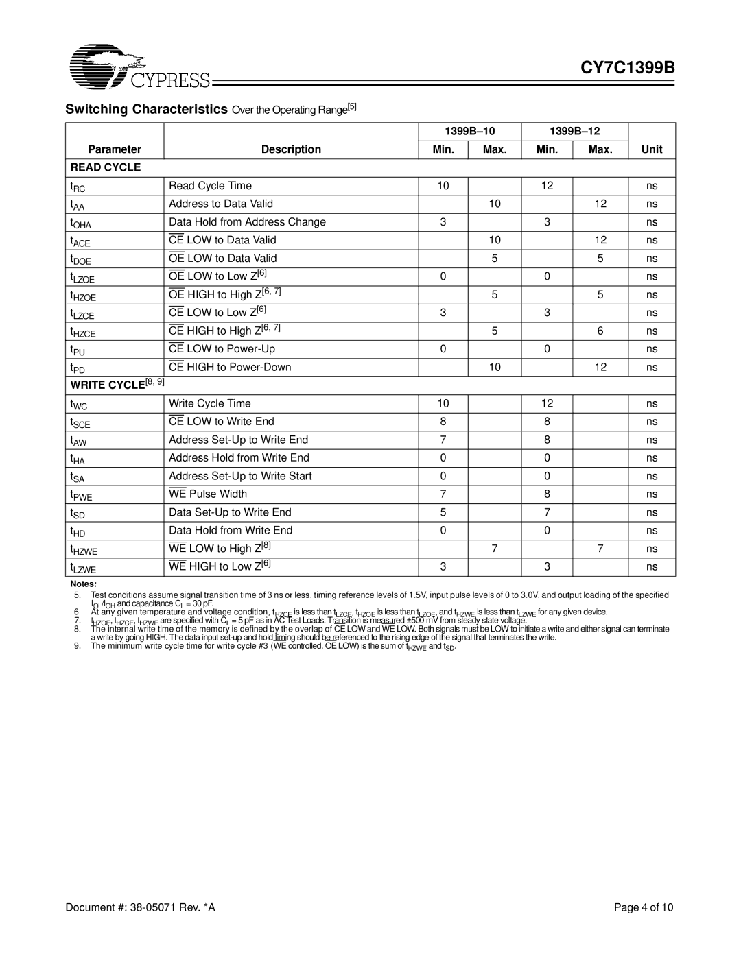
Cypress CY7C1399B manual Switching Characteristics Over the Operating Range5

CY7C1399B specifications

The Cypress CY7C1399B is a high-performance static random-access memory (SRAM) device that belongs to the family of asynchronous CMOS SRAMs. It is designed to deliver superior speed and efficiency, making it ideal for a multitude of applications in various fields, including telecommunications, automotive, and consumer electronics.

One of the key features of the CY7C1399B is its high-speed operation, capable of achieving access times as low as 12 nanoseconds. This allows for rapid data retrieval, which is crucial in applications requiring fast data processing and real-time performance. Moreover, it operates with a single supply voltage of 2.0V to 3.6V, providing flexibility for power-sensitive designs.

The chip comes with a capacity of 16 megabits, which enables it to store substantial amounts of data. Furthermore, it features a burst mode operation that allows for efficient access to multiple consecutive data locations. This capability makes it particularly useful in applications such as video processing, where quick data retrieval is essential.

Another prominent characteristic of the CY7C1399B is its low power consumption. The device boasts both active and standby power modes, which help minimize energy usage, making it suitable for battery-operated devices. This is increasingly becoming a vital factor for consumer electronics, where energy efficiency is a priority.

In terms of interface, the CY7C1399B uses a conventional parallel interface, compatible with a variety of microcontrollers and processors. The device also supports an asynchronous read and write operation, which simplifies integration into existing systems.

The chip is built using advanced 0.18-micron CMOS technology, which not only enhances its performance but also contributes to its reliability and durability. This technology allows the CY7C1399B to achieve high integration density, resulting in a smaller footprint on printed circuit boards (PCBs).

With a combination of high-speed operational characteristics, low power consumption, and substantial data capacity, the Cypress CY7C1399B stands out as an excellent choice for designers seeking efficient memory solutions that can support the demands of modern electronic systems.