Appendix A: DI/DO Specifications
DI/DO Specifications
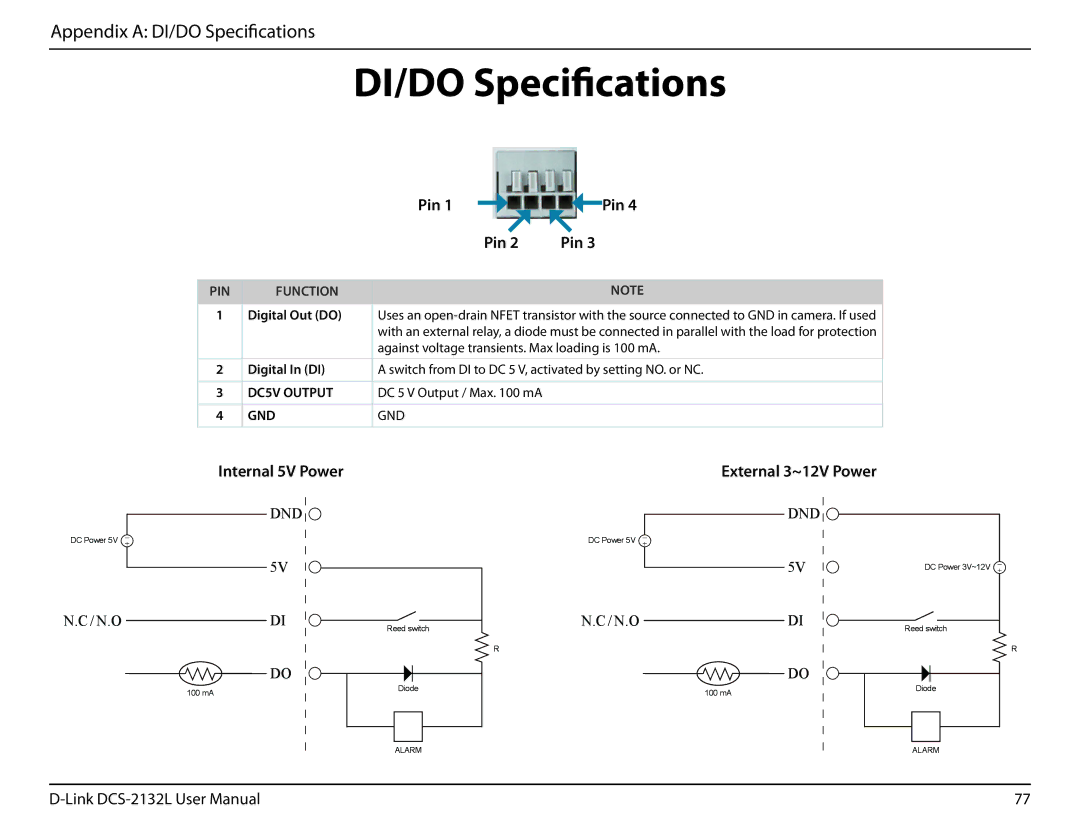
Pin 1 |
|
|
|
| Pin 4 |
|
| ||||
| Pin 2 | Pin 3 | |||
PIN
1
2
3
4
FUNCTION
Digital Out (DO)
Digital In (DI)
DC5V OUTPUT
GND
NOTE
Uses an
A switch from DI to DC 5 V, activated by setting NO. or NC.
DC 5 V Output / Max. 100 mA
GND
Internal 5V Power | External 3~12V Power |
DC Power 5V ![]()
N.C / N.O
DND ![]()
5V |
|
DI | Reed switch |
|
DC Power 5V ![]()
N.C / N.O
DND |
|
5V | DC Power 3V~12V |
DI | Reed switch |
|
100 mA
DO |
Diode |
RR
| DO |
100 mA | Diode |
|
ALARM | ALARM |
77 |