CIRCUIT OPERATION
1-3) PB MODE
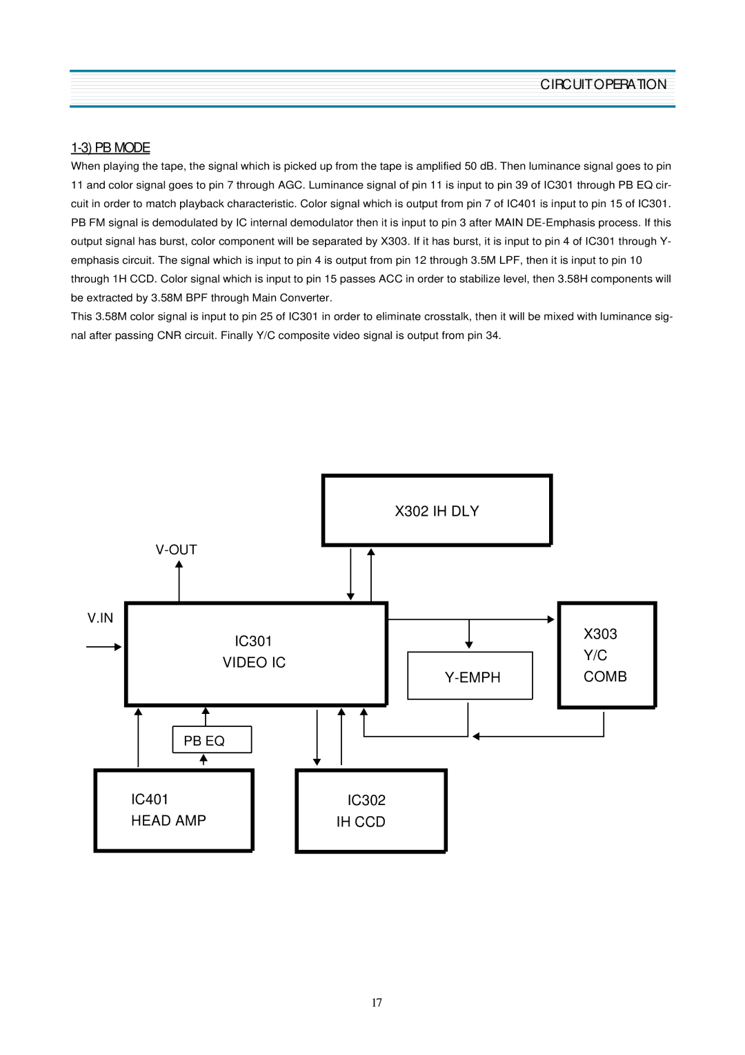
When playing the tape, the signal which is picked up from the tape is amplified 50 dB. Then luminance signal goes to pin 11 and color signal goes to pin 7 through AGC. Luminance signal of pin 11 is input to pin 39 of IC301 through PB EQ cir- cuit in order to match playback characteristic. Color signal which is output from pin 7 of IC401 is input to pin 15 of IC301. PB FM signal is demodulated by IC internal demodulator then it is input to pin 3 after MAIN
This 3.58M color signal is input to pin 25 of IC301 in order to eliminate crosstalk, then it will be mixed with luminance sig- nal after passing CNR circuit. Finally Y/C composite video signal is output from pin 34.
X302 IH DLY
V.IN
IC301
VIDEO IC
PB EQ
X303
Y/C
COMB
| IC401 |
|
|
| IC302 |
|
| HEAD AMP |
|
|
| IH CCD |
|
|
|
|
|
|
|
|
|
|
|
|
|
|
|
17