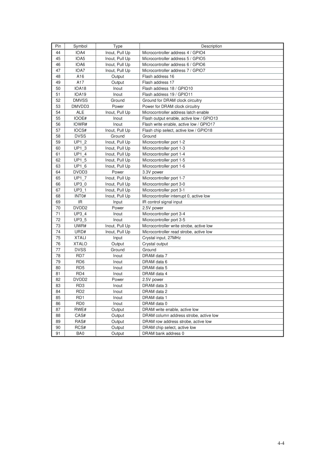
Pin | Symbol | Type | Description |
44 | IOA4 | Inout, Pull Up | Microcontroller address 4 / GPIO4 |
45 | IOA5 | Inout, Pull Up | Microcontroller address 5 / GPIO5 |
46 | IOA6 | Inout, Pull Up | Microcontroller address 6 / GPIO6 |
47 | IOA7 | Inout, Pull Up | Microcontroller address 7 / GPIO7 |
48 | A16 | Output | Flash address 16 |
49 | A17 | Output | Flash address 17 |
50 | IOA18 | Inout | Flash address 18 / GPIO10 |
51 | IOA19 | Inout | Flash address 19 / GPIO11 |
52 | DMVSS | Ground | Ground for DRAM clock circuitry |
53 | DMVDD3 | Power | Power for DRAM clock circuitry |
54 | ALE | Inout, Pull Up | Microcontroller address latch enable |
55 | IOOE# | Inout | Flash output enable, active low / GPIO13 |
56 | IOWR# | Inout | Flash write enable, active low / GPIO17 |
57 | IOCS# | Inout, Pull Up | Flash chip select, active low / GPIO18 |
58 | DVSS | Ground | Ground |
59 | UP1_2 | Inout, Pull Up | Microcontroller port |
60 | UP1_3 | Inout, Pull Up | Microcontroller port |
61 | UP1_4 | Inout, Pull Up | Microcontroller port |
62 | UP1_5 | Inout, Pull Up | Microcontroller port |
63 | UP1_6 | Inout, Pull Up | Microcontroller port |
64 | DVDD3 | Power | 3.3V power |
65 | UP1_7 | Inout, Pull Up | Microcontroller port |
66 | UP3_0 | Inout, Pull Up | Microcontroller port |
67 | UP3_1 | Inout, Pull Up | Microcontroller port |
68 | INT0# | Inout, Pull Up | Microcontroller interrupt 0, active low |
69 | IR | Input | IR control signal input |
70 | DVDD2 | Power | 2.5V power |
71 | UP3_4 | Inout | Microcontroller port |
72 | UP3_5 | Inout | Microcontroller port |
73 | UWR# | Inout, Pull Up | Microcontroller write strobe, active low |
74 | URD# | Inout, Pull Up | Microcontroller read strobe, active low |
75 | XTALI | Input | Crystal input, 27MHz |
76 | XTALO | Output | Crystal output |
77 | DVSS | Ground | Ground |
78 | RD7 | Inout | DRAM data 7 |
79 | RD6 | Inout | DRAM data 6 |
80 | RD5 | Inout | DRAM data 5 |
81 | RD4 | Inout | DRAM data 4 |
82 | DVDD2 | Power | 2.5V power |
83 | RD3 | Inout | DRAM data 3 |
84 | RD2 | Inout | DRAM data 2 |
85 | RD1 | Inout | DRAM data 1 |
86 | RD0 | Inout | DRAM data 0 |
87 | RWE# | Output | DRAM write enable, active low |
88 | CAS# | Output | DRAM column address strobe, active low |
89 | RAS# | Output | DRAM row address strobe, active low |
90 | RCS# | Output | DRAM chip select, active low |
91 | BA0 | Output | DRAM bank address 0 |
Page 62
Image 62