CS4340(AUDIO D/A) IC MATERIAL
DECAL
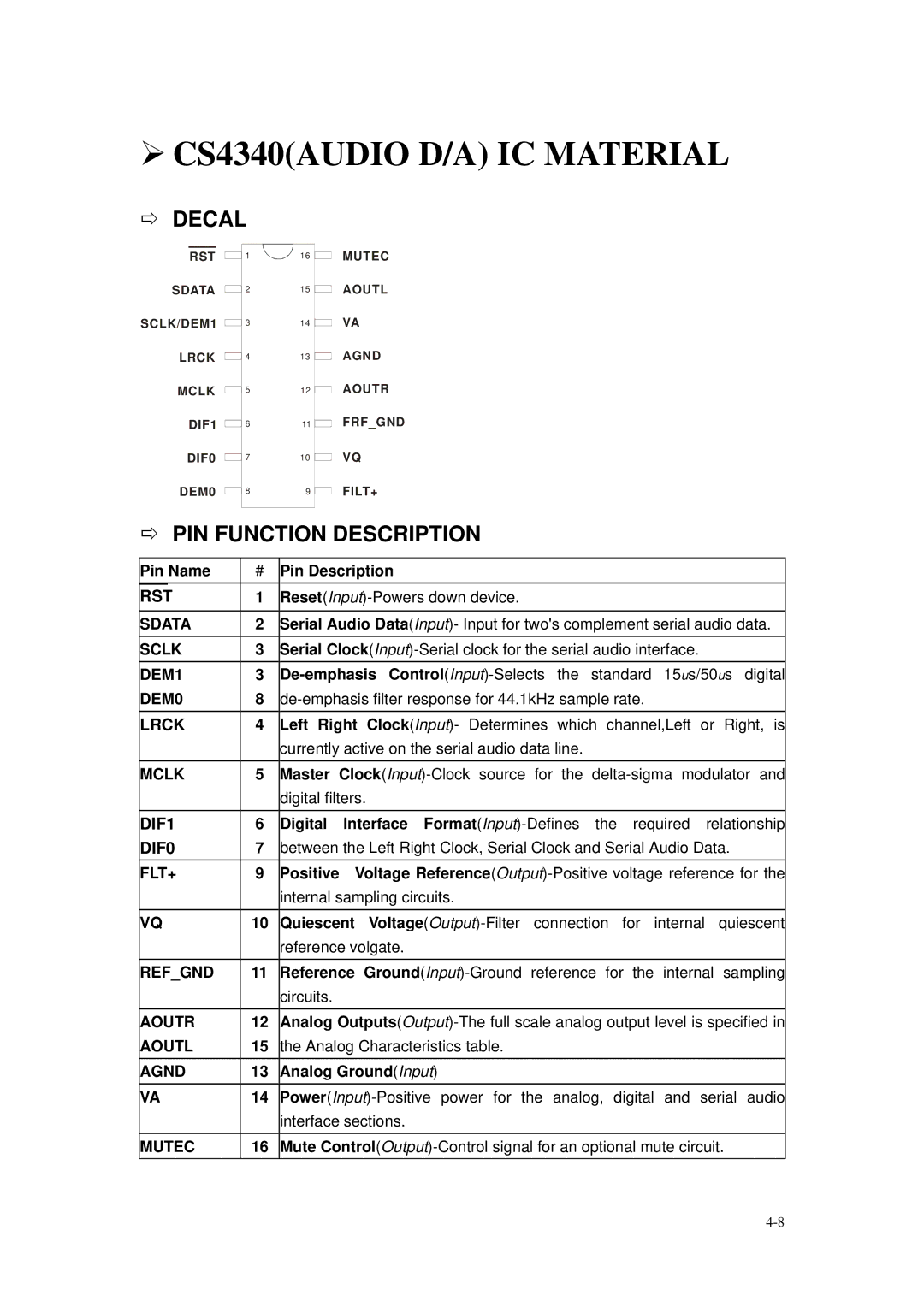
RST
SDATA
SCLK/DEM1
LRCK
MCLK
DIF1
DIF0
DEM0
1 | 16 |
2 | 15 |
3 | 14 |
4 | 13 |
5 | 12 |
6 | 11 |
7 | 10 |
8 | 9 |
MUTEC
AOUTL
VA
AGND
AOUTR
FRF_GND
VQ
FILT+
PIN FUNCTION DESCRIPTION
Pin Name | # | Pin Description |
RST | 1 | |
|
|
|
SDATA | 2 | Serial Audio Data(Input)- Input for two's complement serial audio data. |
SCLK | 3 | Serial |
DEM1 | 3 | |
DEM0 | 8 | |
LRCK | 4 | Left Right Clock(Input)- Determines which channel,Left or Right, is |
|
| currently active on the serial audio data line. |
MCLK | 5 | Master |
|
| digital filters. |
DIF1 | 6 | Digital Interface |
DIF0 | 7 | between the Left Right Clock, Serial Clock and Serial Audio Data. |
FLT+ | 9 | Positive Voltage |
|
| internal sampling circuits. |
VQ | 10 | Quiescent |
|
| reference volgate. |
REF_GND | 11 | Reference |
|
| circuits. |
AOUTR | 12 | Analog |
AOUTL | 15 | the Analog Characteristics table. |
AGND | 13 | Analog Ground(Input) |
VA | 14 | |
|
| interface sections. |
MUTEC | 16 | Mute |