Manuals
/
DCS
/
Lawn and Garden
/
Patio Heater
DCS
PHFS-DW-SS, PHFS-DW-BK, PHFS-DWWT, PHFS-DW-BL, PHFS-DW-GN, PHFS-DW-BZ Assembly Instructions
Models:
PHFS-DW-SS, PHFS-DW-BK, PHFS-DWWT, PHFS-DW-BL, PHFS-DW-GN, PHFS-DW-BZ
1
8
50
50
Download
50 pages
14.33 Kb
5
6
7
8
9
10
11
12
Troubleshooting
Install
Parts list
Warranty
Problem
Assembly Instructions
Cleaning
How to
Precaution
Resolution Des Problemes
Page 8
Image 8
Page 7
Page 9
Page 8
Image 8
Page 7
Page 9
Contents
PHFS-DW-SS PHFS-DW-BK PHFS-DW-WT PHFS-DW-BL PHFS-DW-GN PHFS-DW-BZ
THE PH3 PATIO HEATER
Use and Care Guide Models
PRECAUTION
FOR YOUR SAFETY WHAT TO DO IF YOU SMELL GAS
or by mail DCS Attention Customer Service
A Message To Our Customers
19-20
Table Of Contents
17-18
Safety Practices & Precautions
CHECK THE HEATER IMMEDIATELY IF ANY OF THE FOLLOWING CONDITIONS EXIST
Features
TOOLS NEEDED
Do not tape over the first two threads at the of the intake pipe fig
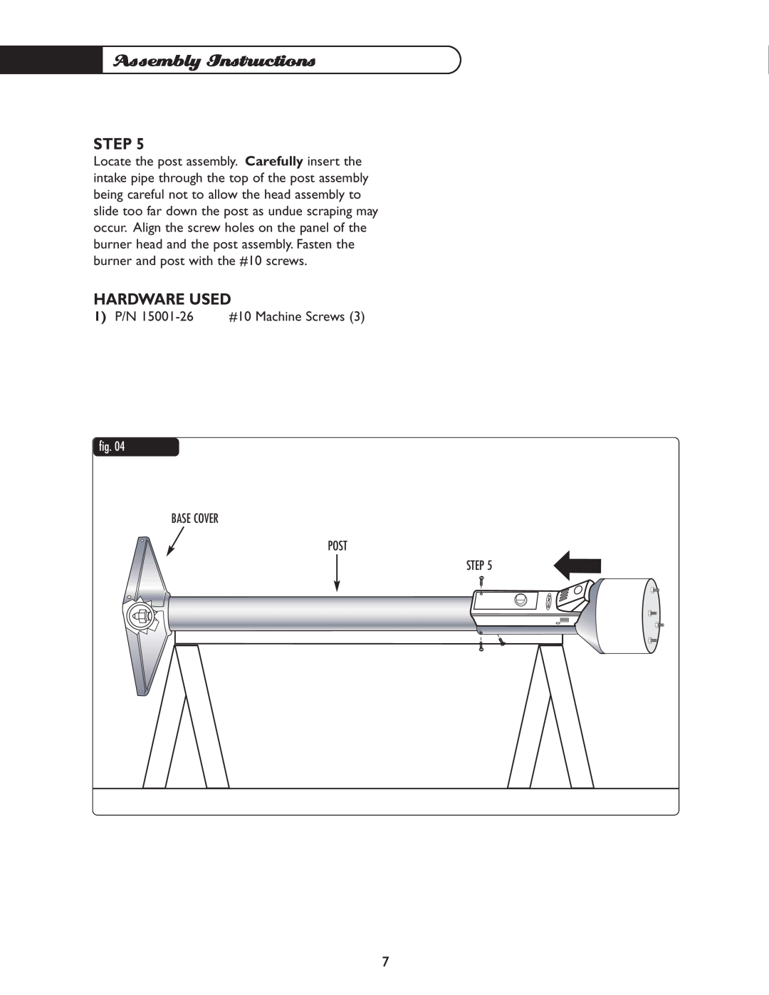
Assembly Instructions
STEP
HARDWARE USED
1 P/N 18159 Reducer Fitting
1 P/N 15001-26 #10 Machine Screws
BASE COVER POST STEP
Assembly Instructions
LP Gas Hook-Up
LP GAS CONNECTION-REFERENCE
CHECK THE FOLLOWING CONNECTIONS
are leak tested at the factory prior to
PRECAUTIONS
Gas Sounding Test
LEAK TEST
TEST POINTS
1 P/N
2 P/N 15019-07 1/4 Cap Acorn Nuts 3 P/N 15005-10 Washers - Split
Washers - Flat
REFLECTOR SPLIT WASHER FLAT WASHER BURNER HEAD
Locating Heater For Use
Lighting And Shutdown
BEFORE TURNING THE GAS SUPPLY “ON”
BEFORE LIGHTING
To light
SPIDER & INSECT WARNING
CLEANING
Storage And Insect Warning
Burner Removal And Installation
BURNER INSTALLATION
Install the burner assembly by reversing the
BURNER REMOVAL
Pilot Cleaning
Troubleshooting
PROBLEM
Call customer service for replacement pilot assembly
available?
Straighten hose Check the burner and orifices for
Emitter glow is uneven
Is there adequate gas supply?
Level heater
Parts List
DESCRIPTION
Post Assembly
Base Assembly
Nylon Washer
Reducer Fitting
Service
HOW TO OBTAIN SERVICE
Warranty
LENGTH OF WARRANTY
DCS WILL PAY FOR
DCS WILL NOT PAY FOR
Page
Page
CHAUFFERETTE DE PATIO PH3
Guide d’utilisation et d’entretien Modèles
ou par courrier DCS Attention Customer Service
À notre clientèle
AVERTISSEMENT
MESURE DE PRÉCAUTION
RESOLUTION DES PROBLEMES
MESURES DE SECURITE ET DE PRECAUTION
DEMONTAGE / INSTALLATION DU BRULEUR
Table des matières
CIRCONSTANCES SUIVANTES
Mesures de sécurité et de précaution
INSPECTEZ IMMEDIATEMENT LA CHAUFFERETTE DANS LES
Caractéristiques
OUTILS NECESSAIRES
Instructions de montage
ETAPE
ETAPE
QUINCAILLERIE UTILISEE
1 Réf. 18159 Réducteur
1 Réf. 15001-26 Vis à métal cal. 10
COUVERCLE DE BASE MÂT ÉTAPE
Instructions de montage
Branchement du gaz
RACCORDEMENT DE LALIMENTATION - REFERENCE
VERIFIEZ SOIGNEUSEMENT LES RACCORDS SUIVANTS
REMARQUE les raccords du brûleur ont été vérifiés à lusine
MESURES DE PRECAUTION
Test détanchéité
DEPISTAGE DES FUITES
POINTS DE DETECTION DES FUITES
ECROU BORGNE
Rondelles plates
REFLECTEUR RONDELLE OUVERTE RONDELLE PLATE BRÛLEUR
Dégagement à respecter
Assurez-vous toujours que laération est suffisante
Allumage et extinction
AVANT DOUVRIR LALIMENTATION EN GAZ
AVANT DALLUMER LA CHAUFFERETTE
Pour allumer
NETTOYAGE
Entreposage et mise en garde relative aux insectes
MISE EN GARDE RELATIVE AUX ARAIGNEES ET AUX INSECTES
DEMONTAGE DU BRULEUR
Démontage et installation du brûleur
INSTALLATION DU BRULEUR
Nettoyage du pilote
Résolution des problèmes
PROBLÈME
nouveau. Y a-t-il une étincelle?
Le réservoir de gaz est-il plein?
Le bouton de commande est-il tourné à fond dans le sens contraire
PROBLÈME
Le tuyau dalimentation est-il tordu?
Remplissez le réservoir
Pièces de rechange
Soupape dalimentation
Écrous borgnes
réservoir 18 po
Appui du réservoir
Poignée de porte
POUR LOBTENTION DU SERVICE DE GARANTIE
Garantie
DUREE DE LA GARANTIE
DCS COUVRE LES FRAIS SUIVANTS
DCS NE COUVRE PAS LES FRAIS SUIVANTS
Page
Fax 714 372-7001 Customer Service 888
Part No. 17314 Rev. B Litho in USA 01/2002 Réf. 17314 Rev. B
Lithographié aux États-Unis 01/2002
5800 Skylab Road, Huntington Beach, CA 92647 Tel 714
Top
Page
Image
Contents