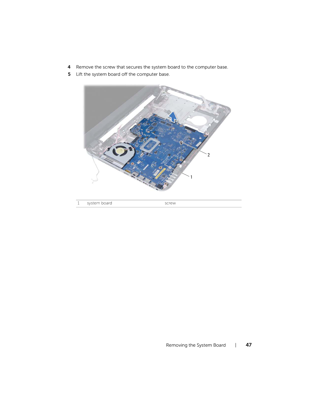
Manuals
/
Dell
/
Computer Equipment
/
Laptop
Dell
5521, 3521 manual Remove the screw that secures the system board to the computer base
Models:
5521
3521
1
47
94
94
Download
94 pages
17.28 Kb
44
45
46
47
48
49
50
51
<
>
Removing the Wireless Mini-Card
Entering the Service Tag in system setup
Removing the Optical-Drive Assembly
Procedure
Removing the Battery
Safety
power-button cable
Flashing the BIOS
Remove the memory module from the memory-module connector
Page 47
Image 47
4
Remove the screw that secures the system board to the computer base.
5
Lift the system board off the computer base.
2
1
1
system board
screw
Removing the System Board
47
Page 46
Page 48
Page 47
Image 47
Page 46
Page 48
Contents
Regulatory type P28F001
Dell Inspiron 3521/5521
Owner’s Manual
Computer model Inspiron 3521/5521 Regulatory model P28F
2012
Notes, Cautions, and Warnings
2012 Dell Inc
Contents
19 Removing the System Board
15 Removing the Wireless Mini-Card
16 Replacing the Wireless Mini-Card
Entering the Service Tag in system setup
30 Replacing the Display Assembly
21 Removing the Coin-Cell Battery
22 Replacing the Coin-Cell Battery
29 Removing the Display Assembly
31 Removing the Display Bezel
Windows
Safety Instructions
Before You Begin
Turn Off Your Computer and Connected Devices
Recommended Tools
After Working Inside Your Computer
10 After Working Inside Your Computer
Procedure
Removing the Battery
12 Removing the Battery
Procedure
Replacing the Battery
Postrequisites
14 Replacing the Battery
1 captive screw
Removing the Memory Modules
Prerequisites
Procedure
1 securing clips
4 Remove the memory module from the memory-module connector
2 memory-module connector
16 Removing the Memory Modules
Postrequisites
Replacing the Memory Modules
Procedure
18 Replacing the Memory Modules
Prerequisites
Removing the Optical-Drive Assembly
Procedure
optical-drive assembly
optical drive
4 Remove the optical-drive bracket from the optical-drive assembly
20 Removing the Optical-Drive Assembly
optical-drive bezel
Postrequisites
Replacing the Optical-Drive Assembly
Procedure
22 Replacing the Optical-Drive Assembly
Prerequisites
Removing the Hard-Drive Assembly
Procedure
pull-tab
24 Removing the Hard-Drive Assembly
hard-drive assembly
5 Lift the hard-drive bracket off the hard drive
Postrequisites
Replacing the Hard-Drive Assembly
Procedure
26 Replacing the Hard-Drive Assembly
plastic scribe
Removing the Keyboard
Procedure
Prerequisites
28 Removing the Keyboard
4 Turn the keyboard over and place it on the palm-rest assembly
6 Lift the keyboard off the palm-rest assembly
connector latch
Postrequisites
Replacing the Keyboard
Procedure
30 Replacing the Keyboard
1 screws
Removing the Palm-Rest
Procedure
Prerequisites
32 Removing the Palm-Rest
power-button cable
3 connector latches
3 Turn the computer over and open the display as far as possible
screws
5 Remove the screws that secure the palm-rest to the system board
7 Lift the palm-rest off the computer base
Removing the Palm-Rest
34 Removing the Palm-Rest
Postrequisites
Replacing the Palm-Rest
Procedure
36 Replacing the Palm-Rest
Prerequisites
Removing the Wireless Mini-Card
38 Removing the Wireless Mini-Card
Procedure
Procedure
Replacing the Wireless Mini-Card
1 Replace the palm-rest. See Replacing the Palm-Rest on page
Postrequisites
Prerequisites
Removing the I/O Board
42 Removing the I/O Board
Procedure
1 Remove the screw that secures the I/O board to the computer base
3 Gently lift and remove the I/O board off the computer base
Postrequisites
Replacing the I/O Board
Procedure
44 Replacing the I/O Board
Prerequisites
Removing the System Board
tape
Procedure
power-adapter-port cable
display cable
system board
4 Remove the screw that secures the system board to the computer base
5 Lift the system board off the computer base
Removing the System Board
48 Removing the System Board
Postrequisites
Entering the Service Tag in system setup
Replacing the System Board
Procedure
50 Replacing the System Board
Prerequisites
Removing the Coin-Cell Battery
1 Turn the system board over and place it on a flat surface
Procedure
52 Removing the Coin-Cell Battery
coin-cell battery
Postrequisites
Replacing the Coin-Cell Battery
Procedure
54 Replacing the Coin-Cell Battery
Prerequisites
Removing the Heat-Sink
screw
Procedure
3 Lift the heat-sink off the system board
56 Removing the Heat-Sink
Postrequisites
Replacing the Heat-Sink
Procedure
58 Replacing the Heat-Sink
Prerequisites
Removing the Fan
3 fan cable
Procedure
screw
Postrequisites
Replacing the Fan
Procedure
62 Replacing the Fan
Prerequisites
Removing the Speakers
tape
Procedure
2 Lift and remove the LED silicon tubes off the computer base
64 Removing the Speakers
speakers
speaker cable routing
66 Removing the Speakers
Postrequisites
Replacing the Speakers
Procedure
68 Replacing the Speakers
Prerequisites
Removing the Display Assembly
1 Peel the tape that secures the display cable to the system board
Procedure
70 Removing the Display Assembly
wireless mini-card cables
screws
display assembly
3 power adapter-port cable
72 Removing the Display Assembly
Postrequisites
Replacing the Display Assembly
Procedure
74 Replacing the Display Assembly
Prerequisites
Removing the Display Bezel
1 hinge covers
Procedure
3 Remove the display bezel off the display back-cover
76 Removing the Display Bezel
Postrequisites
Replacing the Display Bezel
Procedure
78 Replacing the Display Bezel
Prerequisites
Removing the Display Hinges
screws
Procedure
2 Lift the display hinges off the display back-cover
80 Removing the Display Hinges
Postrequisites
Replacing the Display Hinges
Procedure
82 Replacing the Display Hinges
Prerequisites
Removing the Display Panel
display back-cover
Procedure
2 Gently lift the display panel and turn it over
84 Removing the Display Panel
tape
3 Peel the tape that is adhered over the display cable
Removing the Display Panel
display cable
86 Removing the Display Panel
Postrequisites
Replacing the Display Panel
Procedure
88 Replacing the Display Panel
Prerequisites
Removing the Camera Module
tape
Procedure
screw
camera module
Postrequisites
Replacing the Camera Module
Procedure
92 Replacing the Camera Module
Flashing the BIOS
94 Flashing the BIOS