Installation 15 |
| 16 Installation | |
|
|
|
|
|
|
|
|
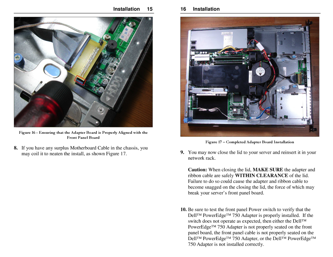
Figure 16 - Ensuring that the Adapter Board is Properly Aligned with the
Front Panel Board
8.If you have any surplus Motherboard Cable in the chassis, you may coil it to neaten the install, as shown Figure 17.
Figure 17 – Completed Adapter Board Installation
9.You may now close the lid to your server and reinsert it in your network rack.
Caution: When closing the lid, MAKE SURE the adapter and ribbon cable are safely WITHIN CLEARANCE of the lid. Failure to do so could cause the adapter and ribbon cable to become snagged on the closing the lid, the force of which may break your server’s front panel board.
10.Be sure to test the front panel Power switch to verify that the
Dell™ PowerEdge™ 750 Adapter is properly installed. | If the |
switch does not operate as expected, then either the Dell™ | |
PowerEdge™ 750 Adapter is not properly seated on th | e front |
panel board, the front panel cable is not properly seated on the
Dell™ PowerEdge™ 750 Adapter, or the Dell™ PowerEdg | e™ |
750 Adapter is not installed correctly. |
|