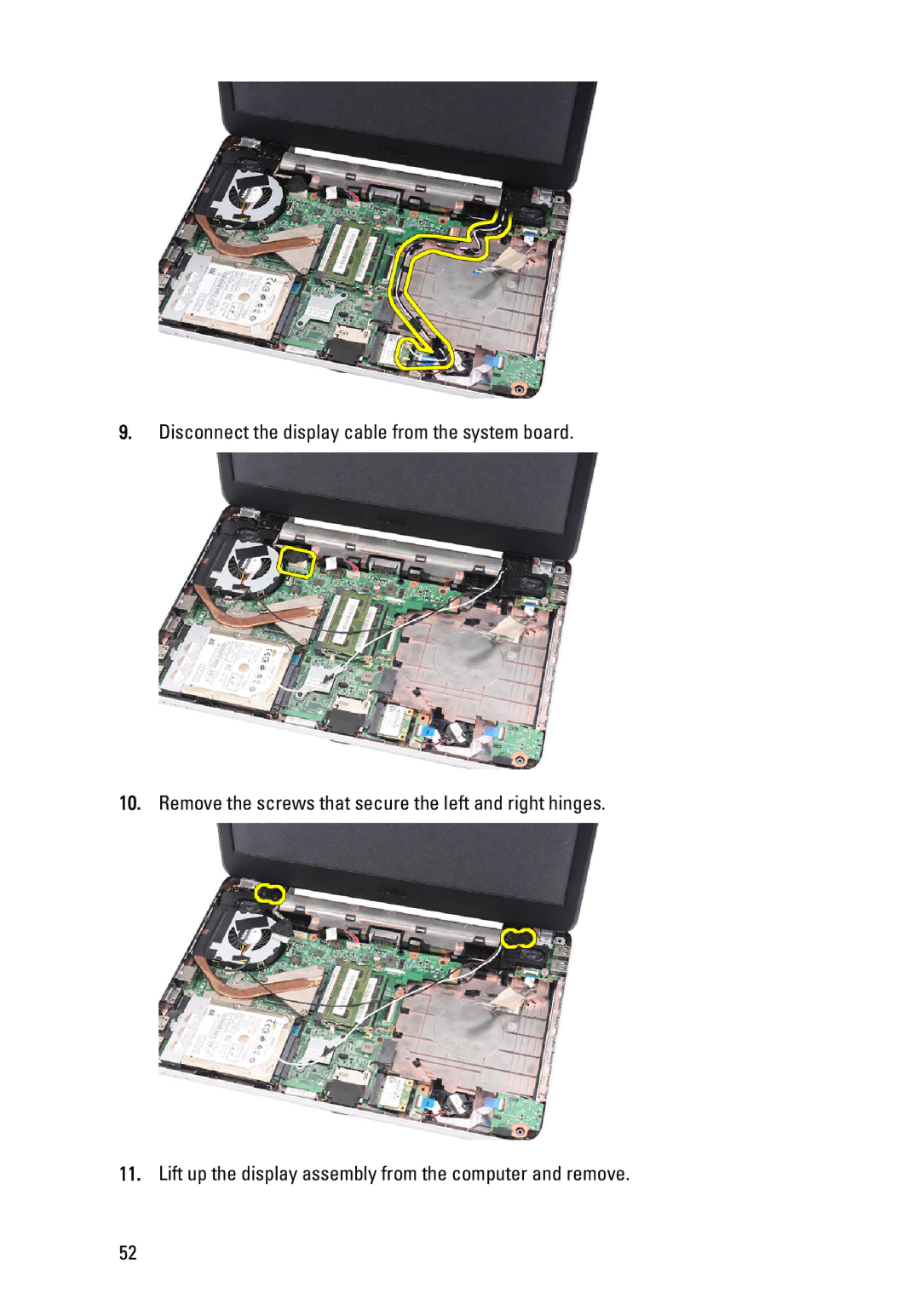
Manuals
/
Dell
/
Computer Equipment
/
Laptop
Dell
P22G owner manual Disconnect the display cable from the system board
Models:
P22G
1
52
83
83
Download
83 pages
49.42 Kb
49
50
51
52
53
54
55
56
<
>
Troubleshooting
Specs
Install
Dimension
Save current configuration and exit System Setup
Removing The Wireless Local Area Network WLAN Card
Entering System Setup
Removing The CPU Fan Assembly And The Heatsink
Follow the procedures in Before Working On Your Computer
Remove the battery
Page 52
Image 52
9.
Disconnect the display cable from the system board.
10.
Remove the screws that secure the left and right hinges.
11.
Lift up the display assembly from the computer and remove.
52
Page 51
Page 53
Page 52
Image 52
Page 51
Page 53
Contents
Dell Vostro 1440/1450 Owners Manual
Regulatory Model P22G Regulatory Type P22G001, P22G003
Information in this publication is subject to change without notice
Notes, Cautions, and Warnings
2011 Dell Inc. All rights reserved
Contents
11 Removing The Wireless Local Area Network WLAN Card
24 Entering System Setup
25 Diagnostic Beep Codes
26 Specifications
22 Removing The Display Panel
Page
Working on Your Computer
Before Working Inside Your Computer
2. Turn off your computer see Turning Off Your Computer
Turning Off Your Computer
Recommended Tools
After Working Inside Your Computer
2. Connect any telephone or network cables to your computer
Removing The Battery
Installing The Battery
1. Follow the procedures in Before Working On Your Computer
2. Slide the release latches to unlock the battery
Page
Removing The Secure Digital SD Card
2. Press in on the SD memory card to release it from the computer
3. Slide the memory card out of the computer
1. Follow the procedures in Before Working On Your Computer
Installing The Secure Digital SD Card
2. Follow the procedures in After Working Inside Your Computer
2. Remove the battery
Removing The Hinge Cover
3. Remove the screws that secure the hinge cover
4. Flip the computer around and remove the hinge cover
Installing The Hinge Cover
4. Follow the procedures in After Working Inside Your Computer
Removing The Keyboard
4. Flip the keyboard over and lay it on the palm rest
5. Disconnect the keyboard cable from the system board
1. Follow the procedures in Before Working On Your Computer
Installing The Keyboard
4. Install the battery
5. Follow the procedures in After Working Inside Your Computer
6. Remove the keyboard from the computer
2. Remove the battery 3. Remove the keyboard
Removing The Optical Drive
4. Remove the screw that secures the optical drive
1. Follow the procedures in Before Working On Your Computer
Installing The Optical Drive
3. Install the keyboard 4. Install the battery
2. Tighten the screw to secure the optical drive to the computer
5. Follow the procedures in After Working Inside Your Computer
Removing The Memory Module
5. Remove the memory module from the computer
1. Follow the procedures in Before Working On Your Computer
2. Remove the battery 3. Remove the keyboard
Installing The Memory Module
1. Insert the memory module into the memory socket
3. Install the keyboard 4. Install the battery
5. Follow the procedures in After Working Inside Your Computer
Removing The Palm Rest
4. Remove the screws that secure the bottom base
6. Remove the screws that secure the palm rest to the computer
1. Follow the procedures in Before Working On Your Computer
Installing The Palm Rest
8. Follow the procedures in After Working Inside Your Computer
Removing The Power Button Board
1. Follow the procedures in Before Working On Your Computer
Installing The Power Button Board
8. Follow the procedures in After Working Inside Your Computer
Removing The Hard Drive
5. Slide the hard drive and lift it out of the computer
1. Follow the procedures in Before Working On Your Computer
2. Remove the battery 3. Remove the keyboard 4. Remove the palm rest
Installing The Hard Drive
1. Install the hard drive bracket to the hard drive
4. Install the palm rest 5. Install the keyboard
6. Install the battery
Removing The Wireless Local Area Network WLAN Card
5. Disconnect any antennae connected to the WLAN card
6. Pry the latch to release the WLAN card from its compartment
1. Follow the procedures in Before Working On Your Computer
Installing The Wireless Local Area Network WLAN Card
7. Remove the WLAN card from the computer
1. Slide the WLAN card into its slot
2. Clip on the WLAN card to the latch to secure it in place
Removing The Coin-Cell Battery
5. Disconnect the coin-cell battery cable from the system board
6. Remove the coin-cell battery from the computer
1. Follow the procedures in Before Working On Your Computer
Installing The Coin-Cell Battery
1. Install the coin-cell battery to the coin-cell battery compartment
2. Connect the coin-cell battery cable to the system board
3. Install the palm rest 4. Install the keyboard
6. Lift up and remove the coin-cell battery from its compartment
Removing The Audio Board
7. Disconnect the audio board cable from the system board
1. Follow the procedures in Before Working On Your Computer
8. Pry the latch to release the audio board
9. Remove the audio board from the computer
Installing The Audio Board
8. Follow the procedures in After Working Inside Your Computer
Page
Removing The USB Board
4. Remove the optical drive
5. Remove the palm rest
6. Disconnect the USB board cable from the system board
Installing The USB Board
8. Follow the procedures in After Working Inside Your Computer
Removing The CPU Fan Assembly And The Heatsink
5. Disconnect the CPU fan cable from the system board
1. Follow the procedures in Before Working On Your Computer
2. Remove the battery 3. Remove the keyboard 4. Remove the palm rest
Installing The CPU Fan Assembly And The Heatsink
7. Follow the procedures in After Working Inside Your Computer
5. Remove the heatsink and the CPU fan assembly
Removing The Processor
6. Rotate the processor-cam screw in a counter-clockwise direction
7. Lift up the processor and remove it from the computer
Installing The Processor
3. Install the CPU fan assembly and the heatsink
4. Install the palm rest 5. Install the keyboard
6. Install the battery
10. Remove the heatsink and the CPU fan assembly
Removing The System Board
3. Remove the SD memory card
4. Remove the keyboard
Installing The System Board
5. Install the heatsink and the CPU fan assembly
9. Install the memory module 10. Install the optical drive
11. Install the keyboard
12. Install the SD memory card
13. Install the battery
Page
11. Remove the heatsink and the CPU fan assembly
15. Remove the display assembly
Removing The Speakers
1. Follow the procedures in Before Working On Your Computer
18. Press the securing latches and lift up the right speaker
Installing The Speakers
3. Install the display assembly
7. Install the heatsink and the CPU fan assembly
15. Install the SD memory card
Page
Removing The Display Assembly
2. Remove the battery 3. Remove the hinge cover
5. Remove the optical drive
6. Remove the palm rest
9. Disconnect the display cable from the system board
11. Lift up the display assembly from the computer and remove
10. Remove the screws that secure the left and right hinges
Installing The Display Assembly
11. Follow the procedures in After Working Inside Your Computer
Page
1. Follow the procedures in Before Working On Your Computer
Removing The Display Bezel
2. Remove the battery
Installing The Display Bezel
1. Align the display bezel in line with the top cover
3. Install the battery
4. Follow the procedures in After Working Inside Your Computer
Removing The Camera
3. Remove the display bezel
4. Disconnect the camera cable from the camera module
5. Pry the latch, lift up the camera, and remove
Installing The Camera
3. Install the display bezel 4. Install the battery
1. Insert and align the camera module to its compartment
2. Connect the camera cable to the camera module
7. Remove the display assembly 8. Remove the display bezel
Removing The Display Panel
9. Disconnect the camera cable from the camera module
10. Remove the screws that secure the display brackets and hinges
12. Release the display cable from the left hinge
11. Release the wireless antennae from the right hinge
13. Lift up the display panel and brackets from the display top cover
Installing The Display Panel
8. Install the display assembly
9. Install the palm rest 10. Install the optical drive
11. Install the keyboard 12. Install the hinge cover
13. Install the battery
14. Follow the procedures in After Working Inside Your Computer
Removing The Display Cable
9. Remove the display panel
10. Peel off the tape covering the display connection
11. Disconnect the display cable from the display panel
Installing The Display Cable
6. Install the display assembly
11. Install the battery
12. Follow the procedures in After Working Inside Your Computer
Page
System Setup Overview
Entering System Setup
System Setup Screens
Displays information on any selected item in the System Setup
Exit from current view or switch the current view to the Exit
Save current configuration and exit System Setup
Up Arrow or Down Arrow
System Setup Options
Main
Advanced
Enable or disable the power
Enable or disable the USB
Enables or disables adapter
Security
Boot
Exit
Page
Cause and Troubleshooting Steps
Diagnostic Beep Codes
Code
Battery Status Lights
Device Status Lights
Specifications
System Information
Processor
Memory
microphone-in/stereo headphones/external
Audio
Video
24-bit analog-to-digital and digital-to-analog
Ports and Connectors
internal wireless local area network WLAN
three 4-pin USB 2.0-compliant connectors
Dimensions Vostro 1440/Vostro
Battery
Display
Keyboard
Touchpad
Battery
approximately 4 hours when the computer is
AC Adapter
Vostro 1440 / Vostro 1450 / Vostro
AC Adapter
Physical
Environmental
31.50 mm to 34.70 mm 1.24 inches to
Airborne contaminant level
G1 as defined by ISA-71.04-1985
Page
Contacting Dell
Contacting Dell