Dell
3.11 Control Panel/LCD
The PowerEdge R515 includes one of the following control panel configurations:
∙LCD panel (8 hard drive chassis only)
∙LED panel (12 hard drive chassis only)
3.11.1 LCD Panel Configuration
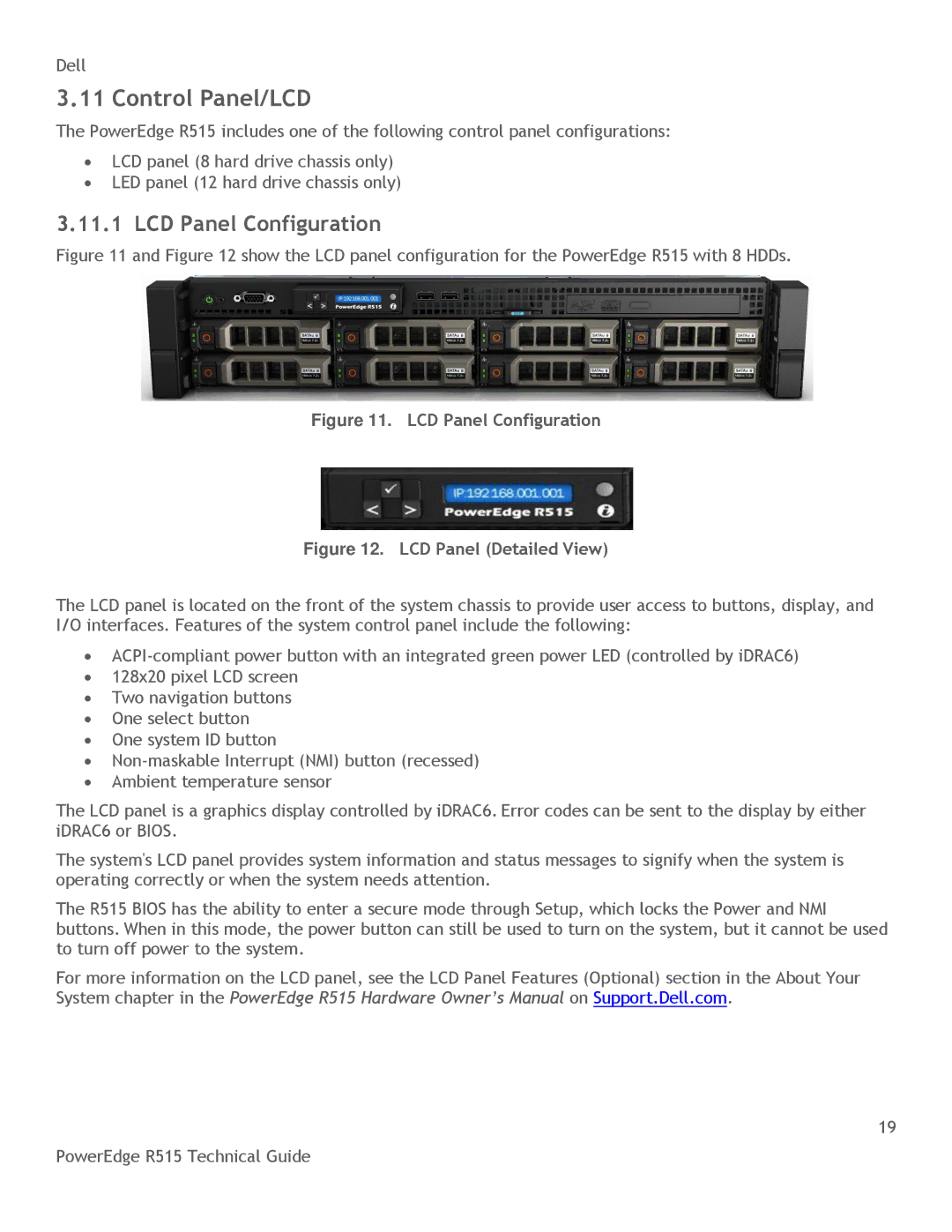
Figure 11 and Figure 12 show the LCD panel configuration for the PowerEdge R515 with 8 HDDs.
Figure 11. LCD Panel Configuration
Figure 12. LCD Panel (Detailed View)
The LCD panel is located on the front of the system chassis to provide user access to buttons, display, and I/O interfaces. Features of the system control panel include the following:
∙
∙128x20 pixel LCD screen
∙Two navigation buttons
∙One select button
∙One system ID button
∙
∙Ambient temperature sensor
The LCD panel is a graphics display controlled by iDRAC6. Error codes can be sent to the display by either iDRAC6 or BIOS.
The system's LCD panel provides system information and status messages to signify when the system is operating correctly or when the system needs attention.
The R515 BIOS has the ability to enter a secure mode through Setup, which locks the Power and NMI buttons. When in this mode, the power button can still be used to turn on the system, but it cannot be used to turn off power to the system.
For more information on the LCD panel, see the LCD Panel Features (Optional) section in the About Your System chapter in the PowerEdge R515 Hardware Owner’s Manual on Support.Dell.com.
19
PowerEdge R515 Technical Guide