Dell PowerEdge R710 Systems
September
Contents
Processor Settings Screen
Entering the Uefi Boot Manager Using the Uefi Boot Manager
Uefi Boot Manager Screen Uefi Boot Settings Screen
Using the System Password Using the Setup Password
Entering the iDRAC Configuration Utility
Removing the Front Bezel Installing the Front Bezel
Installing a Hard Drive Into a Hard-Drive
Removing the Cooling Shroud Installing the Cooling Shroud
Installing the Optical Drive
Removing the Fan Bracket
Replacing the Fan Bracket
Installing the Integrated Storage
General Memory Module Installation
107
112
Replacing the System Battery
Installing the Control Panel Display Module
Installing the Control Panel Board
Installing a SAS Backplane
System Diagnostics Features
155
159
160
177
Accessing System Features During Startup
Front-Panel Features and Indicators
Front-Panel Features and Indicators 2.5-Inch Chassis
Power-on indicator
Power button is not accessible
Power button causes the system to
Power to the system is turned off
System error messages
LCD panel displays an error
Indicator on the back flash blue until
LCD menu
LCD Panel Features
Buttons Description Left
Setup Menu
Home Screen
View Menu
Hard-Drive Indicator Patterns for RAID
Carrier
During this time
Back Panel Features and Indicators
Profile, 24.13-cm 9.5-in length
Height, 24.13-cm 9.5-in length or
Indicator, Button, or
Power Indicator Codes
NIC Indicator Codes
Power Supply Status Indicator Power supply status
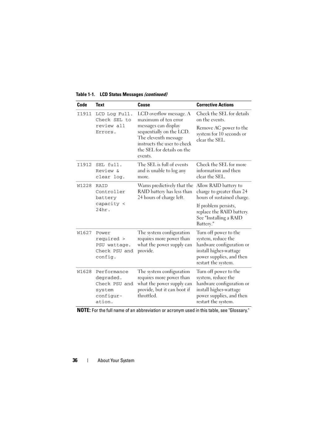
LCD Status Messages
Viewing Status Messages
Removing LCD Status Messages
Error
Disabled
Range. Power
Battery
E122C CPU Power
Fault. Power
E1229
Reseat CPU
CPU configur
CPU or Bios
Error. Power
E1313 Fan
Parity error
Power cycle
Check error
E1610 Power Supply
E1620 Power Supply
Power error
E1624 Lost power
E1626 Power Supply
Error on Bus
Error. Review
E1711 PCI parity
## Device ##
E1715 Fatal I/O
E1716 Chipset Ierr
Bus ## Dev ##
E1717
Fault. Review
Configuration
Reconfigure
E171F PCIe fatal
Configured
But unusable Check DIMMs E2013 Bios unable
E1A14 SAS cable a
Check
E2017 Timer refresh
Timer error
E2019 Parity error. Parity error
E2014
Configur
E201A SuperIO
E201B Keyboard
E201C
During Post Check screen Message E2023 Bios unable
Error on Dimm
Disabled on
E2022 General
Errors
W1627 Power
I1911 LCD Log Full
Check SEL to
System Messages
Rebooting
Power required
Alert! iDRAC6 not
Responding
Alert! Power
System boot
Memory disabled
Fatal error
Bios Update
Nvramclr jumper is installed on system board
CPU x installed
Attempt Failed
Current boot mode
Bootable media is
Configuration on
Is set to Uefi
Please run Setup
Gate A20 failure
Invalid
Information
Accessible USB
Disabled. If
Local keyboard
May not work
Mirror mode
Installed Pairs. Pairs must Be matched Size Geometry
Memory odd/even
Logic failure at
No boot device
No timer tick
Interrupt PCI Bios failed
To install
Read fault
Plug & Play
Quad rank Dimm
Detected after
Seek error
Sata port
Device auto
Seek operation
Setup program
DIMMs should
Following DIMMs should Match in size
Following DIMMs should
Timer chip
Will now reset
Counter 2 failed
Honored. System
System Services
Protected mode
Unable to launch
Image. System
Installed
When in mirror or
Error has caused
System reset
System will Reboot
Configuration is
Recommended Memory Configuration
Performance
Diagnostics Messages
Write fault
Write fault on
Alert Messages
Other Information You May Need
Choosing the System Boot Mode
Using the System Setup Program and Uefi Boot Manager
Entering the System Setup Program
Responding to Error Messages
Using the System Setup Program Navigation Keys
System if any changes were made
System Setup Options
Memory Settings Screen
Main Screen
Option Description Sata Settings
Boot Settings
Boot devices. See Boot Settings Screen
Fans, and memory modules with preconfigured or
Memory Settings Screen
Processor Settings Screen
Sata Settings Screen
Boot Settings Screen
Integrated Devices Screen
PCI IRQ Assignments Screen
Serial Communication Screen
Embedded Server Management Screen
Power Management Screen
System Security Screen
Enables or disables the NMI feature
Exit Screen
Entering the Uefi Boot Manager
Using the Uefi Boot Manager Navigation Keys
Displays the Uefi Boot Manager help file
Other program screens
Uefi Boot Manager Screen
Uefi Boot Settings Screen
System Utilities Screen
System and Setup Password Features
Using the System Password
Using the System Setup Program and Uefi Boot Manager
Using the Setup Password
IDRAC Configuration Utility
Entering the iDRAC Configuration Utility
Installing System Components
Recommended Tools
Inside the System
Page
Front Bezel Optional
Removing the Front Bezel
Installing the Front Bezel
Information Tag
Removing the Information Tag
Replacing the Information Tag
Opening and Closing the System
Opening the System
Closing the System
Lift up the latch on the cover
Hard Drives
Chassis hooks
Mixed SAS/SATA Hard-Drive Configurations
Removing a Hard-Drive Blank
Installing a Hard-Drive Blank
Removing a Hot-Swap Hard Drive
Installing a Hot-Swap Hard Drive
Installing a Hard Drive Into a Hard-Drive Carrier
Removing a Hard Drive From a Hard-Drive Carrier
SAS screw hole
Power Supplies
Removing a Power Supply
Replacing a Power Supply
Removing the Power Supply Blank
Installing the Power Supply Blank
Installing the Internal SD Module
Internal SD Module
Internal SD module connector Control panel board
Release tab
Installing the Internal SD Flash Card
Internal SD Flash Card
Removing the Internal SD Module
Internal USB Memory Key
Removing the Internal SD Flash Card
Removing or Installing a USB Memory Key Control panel board
USB memory key
Installing the Internal USB Cable
Remove the USB cable from the connector on the system board
Internal USB Cable
Removing the Internal USB Cable
Installing an iDRAC6 Enterprise Card
Removing an iDRAC6 Enterprise Card
Card
Retention standoff posts
VFlash Media Optional
NIC Hardware Key
Cooling Shroud
Processors Installing System Components
Removing the Cooling Shroud
Installing the Cooling Shroud
Cooling Fans
Removing a Cooling Fan
Open the system. See Opening the System 100
151
152
Troubleshooting External Connections
Troubleshooting Your System
153
Troubleshooting the Video Subsystem
Troubleshooting a USB Device
Troubleshooting a Serial I/O Device
Troubleshooting a NIC
155
Troubleshooting a Wet System
Troubleshooting a Damaged System
157
Troubleshooting the System Battery
Troubleshooting Power Supplies
Troubleshooting System Cooling Problems
Ensure that none of the following conditions exist
159
Troubleshooting a Fan
Troubleshooting System Memory
160
161
Troubleshooting an Internal SD Card
Troubleshooting an Internal USB Memory Key
163
Troubleshooting an Optical Drive
Troubleshooting a Tape Backup Unit
165
Troubleshooting a Hard Drive
Troubleshooting a Storage Controller
167
Troubleshooting Expansion Cards
169
Troubleshooting the Processors
171
172
Using Dell PowerEdge Diagnostics
System Diagnostics Features
Running the System Diagnostics
173
When to Use the System Diagnostics
Running the System Diagnostics
System Diagnostics Testing Options
Select the testing option in the Main Menu window
Using the Custom Test Options
Selecting Devices for Testing
Selecting Diagnostics Options
Testing Option Function Information Displays test results
Viewing Information and Results
Jumpers and Connectors
System Board Jumpers
Pins 2 and 4 The password feature is enabled
Default System boot
178
Jumper Setting Description
179
System Board Connectors
Expansion-card riser 2 connector
Expansion-card riser 1 connector
180
181
SAS Backplane Board Connectors
Power supply connector for PS2
Power supply connector for PS1
182
Drive 0 drive 3 connectors
Backplane power Bkpln SAS a connector SAS B connector
Drive 3 connector
Backplane power Bppwr
Drive 5 connector
184
Card edge connector
Release button Jumpers and Connectors
Expansion-Card Riser-Board Components and PCIe Buses
185
Cm 9.5-in length Pin collars Card edge connector
186
Disabling a Forgotten Password
Cm 9.5-in length Card edge connector
187
Jumpers and Connectors
Contacting Dell
189
190
191
Amperes AC Alternating current
Glossary
192
CPU Central processing unit. See processor DC Direct current
193
194
195
196
197
System memory See RAM
198
199
200