Installation (continued)
| DC Power | |
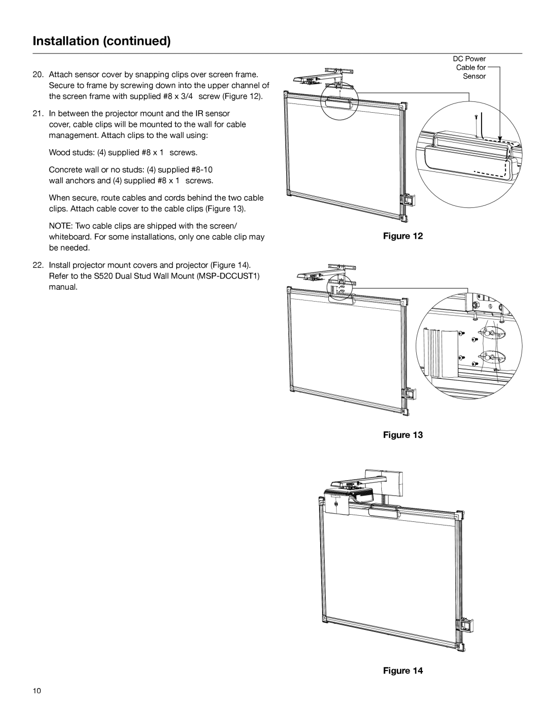
20. Attach sensor cover by snapping clips over screen frame. | Cable for | |
Sensor | ||
Secure to frame by screwing down into the upper channel of |
|
|
the screen frame with supplied #8 x 3/4” screw (Figure 12). |
|
|
|
| |
21. In between the projector mount and the IR sensor cover, cable clips will be mounted to the wall for cable management. Attach clips to the wall using:
Wood studs: (4) supplied #8 x 1” screws.
Concrete wall or no studs: (4) supplied
When secure, route cables and cords behind the two cable clips. Attach cable cover to the cable clips (Figure 13).
NOTE: Two cable clips are shipped with the screen/ |
|
| |
Figure 12 | |||
whiteboard. For some installations, only one cable clip may | |||
be needed. |
|
| |
22. Install projector mount covers and projector (Figure 14). Refer to the S520 Dual Stud Wall Mount
Figure 13
Figure 14
10