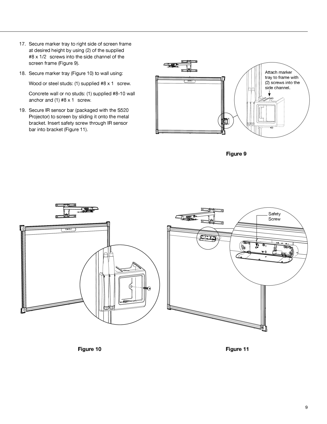
17.Secure marker tray to right side of screen frame at desired height by using (2) of the supplied #8 x 1/2” screws into the side channel of the screen frame (Figure 9).
18.Secure marker tray (Figure 10) to wall using: Wood or steel studs: (1) supplied #8 x 1” screw.
Concrete wall or no studs: (1) supplied
19.Secure IR sensor bar (packaged with the S520 Projector) to screen by sliding it onto the metal bracket. Insert safety screw through IR sensor bar into bracket (Figure 11).
F
Figure 10
Attach marker tray to frame with
(2) screws into the side channel.
Figure 9
Safety
Screw
Figure 11
9