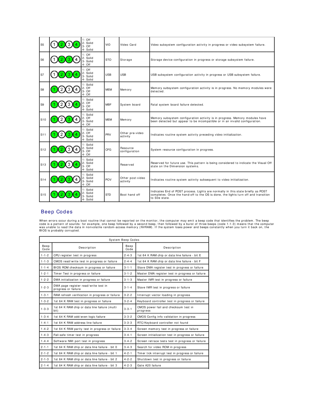
1- Off


S5


2- Solid

VID

Video Card

Video subsystem configuration activity in progress or video subsystem failure.


3- Off


4- Solid


1- Off


S6


2- Solid

STO

Storage

Storage device configuration in progress or storage subsystem failure.


3- Solid


4- Off


1- Off


S7


2- Solid

USB

USB

USB subsystem configuration activity in progress or USB subsystem failure.


3- Solid


4- Solid


1- Solid


S8


2- Off

MEM

Memory

Memory subsystem configuration activity is in progress. No memory modules were


3- Off

detected.


4- Off


1- Solid


S9


2- Off

MBF

System board

Fatal system board failure detected.


3- Off


4- Solid


1- Solid


S10


2- Off

MEM

Memory

Memory subsystem configuration activity is in progress. Memory modules have


3- Solid

been detected but appear to be incompatible or in an invalid configuration.


4- Off


1- Solid


S11


2- Off

PRV

Other pre-video

Indicates routine system activity preceding video initialization.


3- Solid

activity


4- Solid


1- Solid


S12


2- Solid

CFG

Resource

System resource configuration in progress.


3- Off

configuration


4- Off


1- Solid


S13


2- Solid


Reserved

Reserved for future use. This pattern is being considered to indicate the Visual Off


3- Off


state on the Dimension systems.


4- Solid


1- Solid


S14


2- Solid

POV

Other post-video

Indicates routine system activity subsequent to video initialization.


3- Solid

activity


4- Off


1- Solid


Indicates End of POST process. Lights are normally in this state briefly as POST


2- Solid


S15


STD

Boot hand off

completes. Once the hand-off to the OS is done, the lights turn off and transition


3- Solid


to S0e state.


4- Solid


Beep Codes

When errors occur during a boot routine that cannot be reported on the monitor, the computer may emit a beep code that identifies the problem. The beep code is a pattern of sounds: for example, one beep followed by a second beep, then followed by a burst of three beeps (code 1-1-3) means that the computer was unable to read the data in nonvolatile random-access memory (NVRAM). If the system loses power and beeps constantly when you turn it back on, the BIOS is probably corrupted.

System Beep Codes

Beep

Description

Beep

Description

Code

Code


1-1-2

CPU register test in progress

2-4-3

1st 64 K RAM chip or data line failure - bit E


1-1-3

CMOS read/write test in progress or failure

2-4-4

1st 64 K RAM chip or data line failure - bit F


1-1-4

BIOS ROM checksum in progress or failure

3-1-1

Slave DMA register test in progress or failure


1-2-1

Timer Test in progress or failure

3-1-2

Master DMA register test in progress or failure


1-2-2

DMA initialization in progress or failure

3-1-3

Master IMR test in progress or failure


1-2-3

DMA page register read/write test in

3-1-4

Slave IMR test in progress or failure

progress or failure


1-3-1

RAM refresh verification in progress or failure

3-2-2

Interrupt vector loading in progress


1-3-2

1st 64 K RAM test in progress or failure

3-2-4

Keyboard controller test in progress or failure


1-3-3

1st 64 K RAM chip or data line failure (multi

3-3-1

CMOS power fail and checksum test in

bit)

progress


1-3-4

1st 64 K RAM odd/even logic failure

3-3-2

CMOS Config info validation in progress


1-4-1

1st 64 K RAM address line failure

3-3-3

RTC/Keyboard controller not found


1-4-2

1st 64 K RAM parity test in progress or failure

3-3-4

Screen memory test in progress or failure


1-4-3

Fail-safe timer test in progress

3-4-1

Screen initialization test in progress or failure


1-4-4

Software NMI port test in progress

3-4-2

Screen retrace tests test in progress or failure


2-1-1

1st 64 K RAM chip or data line failure - bit 0

3-4-3

Search for video ROM in progress


2-1-2

1st 64 K RAM chip or data line failure - bit 1

4-2-1

Timer tick interrupt test in progress or failure


2-1-3

1st 64 K RAM chip or data line failure - bit 2

4-2-2

Shutdown test in progress or failure


2-1-4

1st 64 K RAM chip or data line failure - bit 3

4-2-3

Gate A20 failure


Page 12
Image 12
Dell T5500 specifications System Beep Codes Description

T5500 specifications

The Dell T5500, part of the Precision series, is a workstation designed for professionals in creative and technical fields who require robust performance while managing complex tasks. Launched as a successor to its predecessor models, the T5500 is characterized by a blend of powerful computing capabilities, expandability, and reliability, making it a suitable choice for applications such as 3D modeling, graphic design, and scientific simulations.

One of the most notable features of the Dell T5500 is its support for dual Intel Xeon processors. This configuration allows for a significant increase in processing power, ideal for resource-intensive applications. Users can configure their machines with up to 12 processing cores, enhancing parallel processing and multitasking capabilities. Additionally, the T5500 offers a substantial memory capacity, supporting up to 96GB of DDR3 RAM, which provides ample headroom for handling large datasets and running multiple applications simultaneously.

Storage options in the T5500 are versatile, accommodating a range of hard drives from traditional HDDs to high-performance SSDs. This flexibility allows professionals to select their desired balance between speed and storage capacity. Furthermore, the tower's design includes multiple drive bays, facilitating easy upgrades or additional storage solutions.

The Dell T5500's graphics capabilities are equally impressive, supporting a variety of professional-grade graphics cards, including NVIDIA Quadro and AMD FirePro models. These cards deliver exceptional visualization performance suited for tasks such as CAD, digital content creation, and video editing. The workstation also includes multiple expansion slots, enabling users to add extra GPUs to elevate graphical rendering capabilities.

Connectivity is another key characteristic of the T5500. It features USB 3.0 ports, offering faster data transfer rates, along with legacy ports for compatibility with older peripherals. Networking options include integrated gigabit Ethernet, ensuring reliable connectivity for collaborative workflows and remote data access.

Designed with reliability in mind, the Dell T5500 includes features such as advanced thermal management to keep components cool during intense workloads, and a tool-less chassis design that simplifies upgrades and maintenance tasks. Furthermore, it adheres to strict energy efficiency standards, making it an environmentally friendly choice for professionals who demand performance without compromising on sustainability.

In summary, the Dell T5500 workstation is a powerful and flexible choice tailored for demanding applications across various industries. Its combination of dual Xeon processors, extensive memory capacity, versatile storage options, high-end graphics support, and robust connectivity make it an invaluable tool for professionals looking to enhance their productivity and streamline their workflows.