ASSEMBLING STAND HANDLE
Insert ends of handle (A) Fig. 5, into the two holes (B) on the right leg and fasten in place using the two cotter pins supplied.
ASSEMBLING STOCK ADVANCE STOP
Assemble the stock advance stop assembly (A) to the hole on the front of the table and tighten the two set screws (B), as shown in Fig. 6.
ASSEMBLING GUARD AND BELT
Open the belt and pulley guard (A) Fig. 7, and position the bottom half of the guard assembly behind the pulleys (B) as shown. Line up the two holes in the bottom of the guard with the two threaded holes in the casting. NOTE: DO NOT COMPLETELY TIGHTEN THE
PULLEY GUARD TO THE CASTING AT THIS TIME. Place a 1/4" flat washer onto a
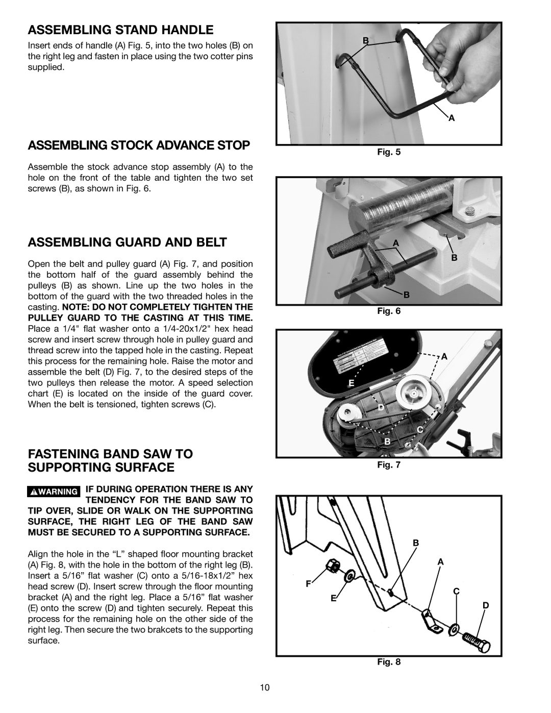
FASTENING BAND SAW TO
SUPPORTING SURFACE
![]() IF DURING OPERATION THERE IS ANY TENDENCY FOR THE BAND SAW TO TIP OVER, SLIDE OR WALK ON THE SUPPORTING
IF DURING OPERATION THERE IS ANY TENDENCY FOR THE BAND SAW TO TIP OVER, SLIDE OR WALK ON THE SUPPORTING
SURFACE, THE RIGHT LEG OF THE BAND SAW MUST BE SECURED TO A SUPPORTING SURFACE.
Align the hole in the “L” shaped floor mounting bracket
(A)Fig. 8, with the hole in the bottom of the right leg (B). Insert a 5/16” flat washer (C) onto a 5/16-18x1/2” hex head screw (D). Insert screw through the floor mounting bracket (A) and the right leg. Place a 5/16” flat washer
(E)onto the screw (D) and tighten securely. Repeat this process for the remaining hole on the other side of the right leg. Then secure the two brakcets to the supporting surface.
B![]()
![]() A
A
Fig. 5
A![]()
![]() B
B
![]() B
B
Fig. 6
![]() A
A
E
D
C
B
Fig. 7
B
A
F
C
E
D
Fig. 8
10