ADJUSTING BLADE GUIDE
BEARINGS
DISCONNECT MACHINE FROM
POWER SOURCE.
![]() E
E
A![]() D
D
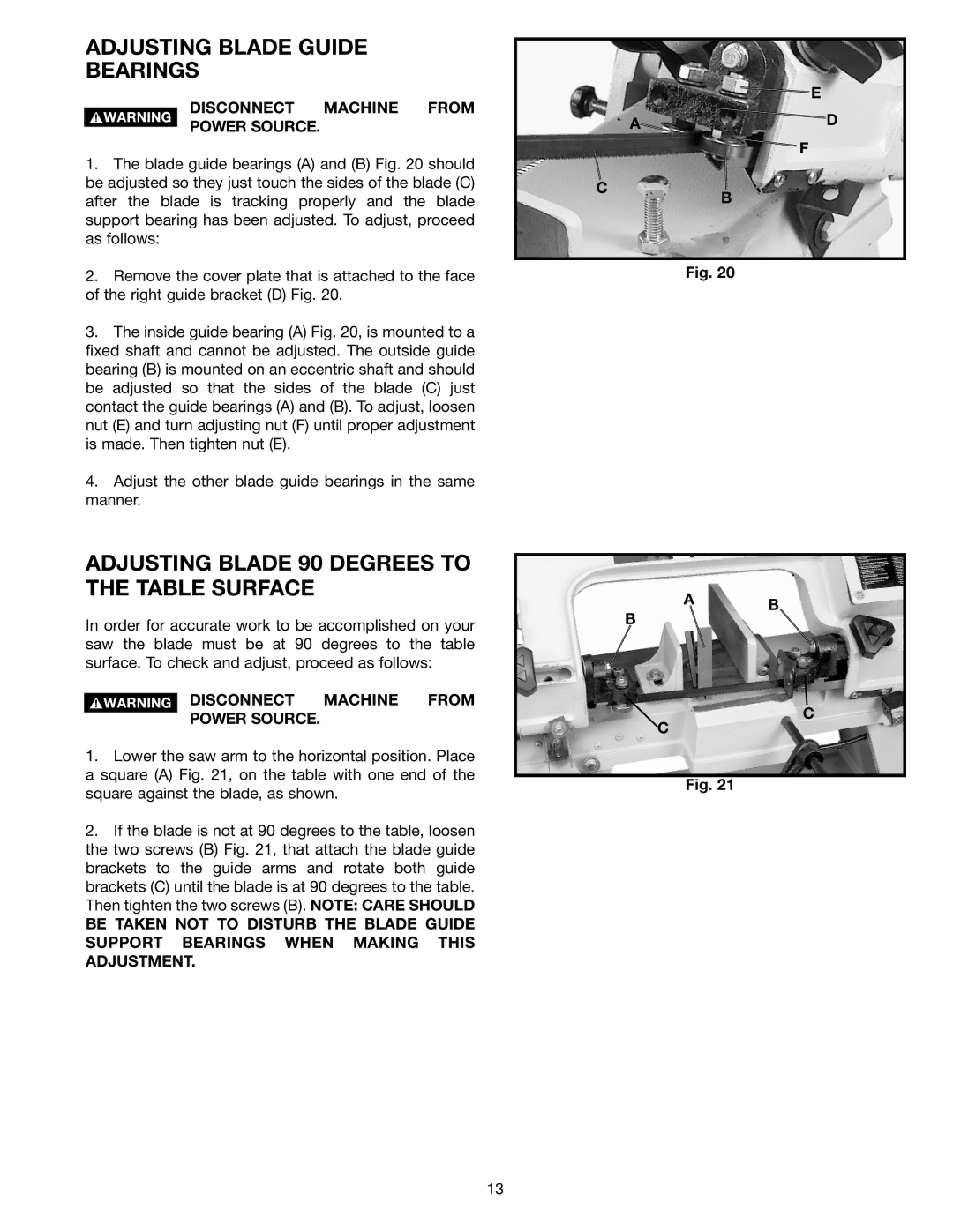
1. The blade guide bearings (A) and (B) Fig. 20 should |
be adjusted so they just touch the sides of the blade (C) |
after the blade is tracking properly and the blade |
support bearing has been adjusted. To adjust, proceed |
as follows: |
C
F
B
2. | Remove the cover plate that is attached to the face |
of the right guide bracket (D) Fig. 20. | |
3. | The inside guide bearing (A) Fig. 20, is mounted to a |
fixed shaft and cannot be adjusted. The outside guide | |
bearing (B) is mounted on an eccentric shaft and should | |
be adjusted so that the sides of the blade (C) just | |
contact the guide bearings (A) and (B). To adjust, loosen | |
nut (E) and turn adjusting nut (F) until proper adjustment | |
is made. Then tighten nut (E). | |
4. | Adjust the other blade guide bearings in the same |
manner. | |
ADJUSTING BLADE 90 DEGREES TO THE TABLE SURFACE
In order for accurate work to be accomplished on your saw the blade must be at 90 degrees to the table surface. To check and adjust, proceed as follows:
DISCONNECT MACHINE FROM
POWER SOURCE.
1.Lower the saw arm to the horizontal position. Place a square (A) Fig. 21, on the table with one end of the square against the blade, as shown.
2.If the blade is not at 90 degrees to the table, loosen the two screws (B) Fig. 21, that attach the blade guide brackets to the guide arms and rotate both guide brackets (C) until the blade is at 90 degrees to the table. Then tighten the two screws (B). NOTE: CARE SHOULD
BE TAKEN NOT TO DISTURB THE BLADE GUIDE SUPPORT BEARINGS WHEN MAKING THIS ADJUSTMENT.
Fig. 20
A B
B
C
C
Fig. 21
13
