OPERATION
STARTING AND STOPPING THE SAW
![]()
![]()
![]()
![]()
![]()
![]()
![]()
![]() Make sure that the switch is in the “OFF" position before plugging cord into outlet. Do not touch the plug’s metal prongs when
Make sure that the switch is in the “OFF" position before plugging cord into outlet. Do not touch the plug’s metal prongs when
unplugging or plugging in the cord
Do not attempt to operate this tool without first connecting it to an
adequate dust collection system
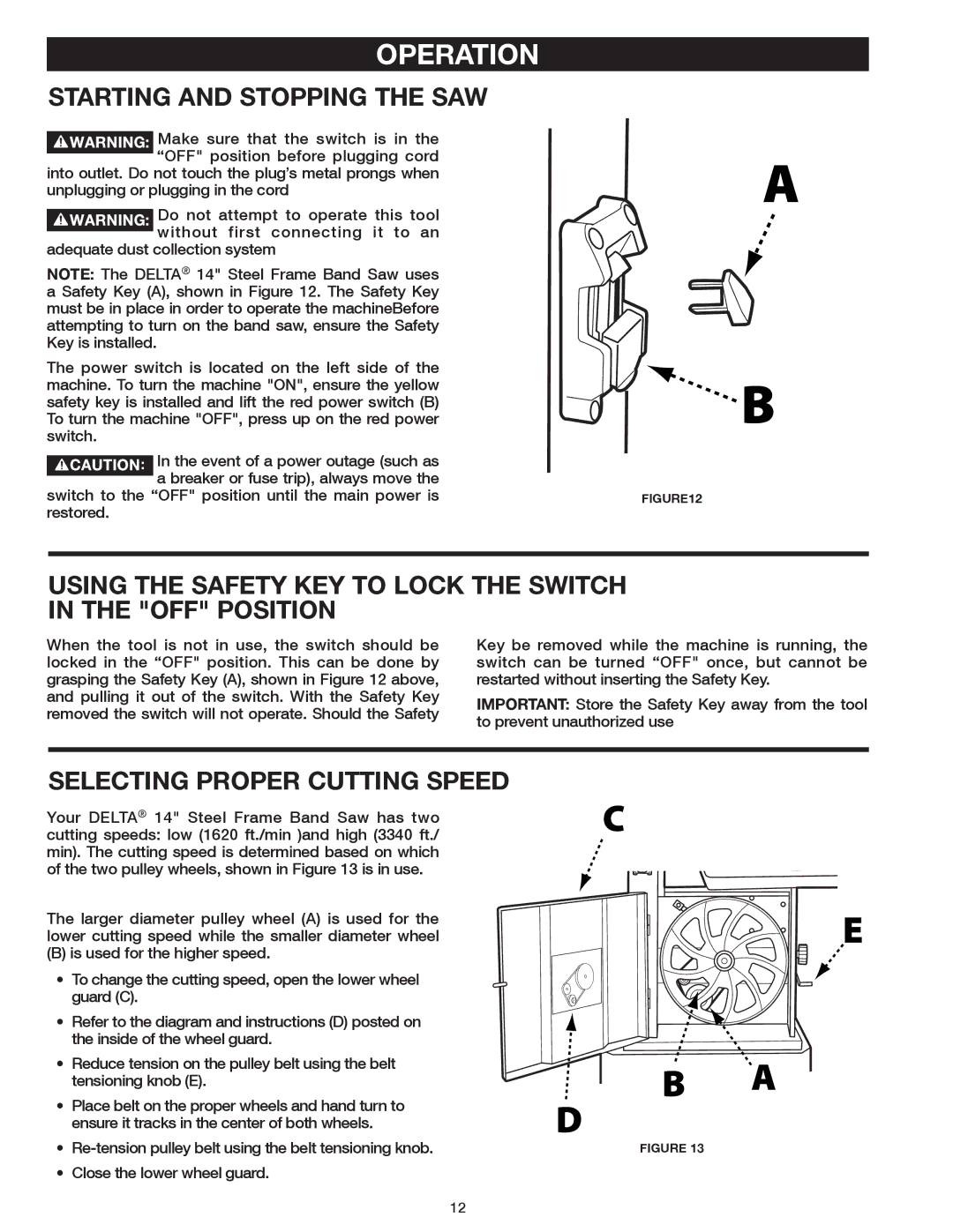
NOTE: The DELTA® 14" Steel Frame Band Saw uses a Safety Key (A), shown in Figure 12. The Safety Key
must be in place in order to operate the machineBefore attempting to turn on the band saw, ensure the Safety
Key is installed.
The power switch is located on the left side of the machine. To turn the machine "ON", ensure the yellow safety key is installed and lift the red power switch (B) To turn the machine "OFF", press up on the red power switch.
In the event of a power outage (such as a breaker or fuse trip), always move the
switch to the “OFF" position until the main power isFigure12 restored.
USING THE SAFETY KEY TO LOCK THE SWITCH IN THE "OFF" POSITION
When the tool is not in use, the switch should be locked in the “OFF" position. This can be done by grasping the Safety Key (A), shown in Figure 12 above, and pulling it out of the switch. With the Safety Key removed the switch will not operate. Should the Safety
Key be removed while the machine is running, the switch can be turned “OFF" once, but cannot be restarted without inserting the Safety Key.
IMPORTANT: Store the Safety Key away from the tool to prevent unauthorized use
SELECTING PROPER CUTTING SPEED
Your DELTA® 14" Steel Frame Band Saw has two cutting speeds: low (1620 ft./min )and high (3340 ft./ min). The cutting speed is determined based on which of the two pulley wheels, shown in Figure 13 is in use.
The larger diameter pulley wheel (A) is used for the lower cutting speed while the smaller diameter wheel
(B) is used for the higher speed.
• To change the cutting speed, open the lower wheel guard (C).
• Refer to the diagram and instructions (D) posted on the inside of the wheel guard.
•Reduce tension on the pulley belt using the belt
tensioning knob (E).
•Place belt on the proper wheels and hand turn to ensure it tracks in the center of both wheels.
• | Figure 13 | |
• | Close the lower wheel guard. |
|
12