3.Remove two mounting screws, one of which is shown at (E) Fig. 2, that are holding motor (F) to the top of stand
(A). IMPORTANT: DO NOT REMOVE CABLE TIE (G)
THAT IS HOLDING SWITCH CORD (H) TO VERTICAL MOUNTING BAR (J), UNLESS YOU ARE USING THE ACCESSORY
ASSEMBLING
MOTOR TO STAND
1.To make the motor assembly easier, turn stand (A) Fig. 3, on its side with two horizontal bars (B) down as shown.
2.Position motor (C) Fig. 3, on two horizontal support bars (B) as shown, and fasten with four 3/4 long carriage bolts, two of which are shown at (D), and four flanged nuts. IMPORTANT: MAKE CERTAIN MOTOR SHAFT (E)
IS ON THE SAME SIDE OF THE STAND AS THE LARGE OPENING IN THE TOP OF THE STAND BEFORE TIGHTENING CARRIAGE BOLTS (D). Further motor alignment will be necessary after band saw is fas- tened to stand.
3.Insert power cord plug (G) Fig. 4, through the bottom hole of the band saw stand.
4.Carefully turn the stand right side up.
G
Fig. 4
Fig. 2
Fig. 3
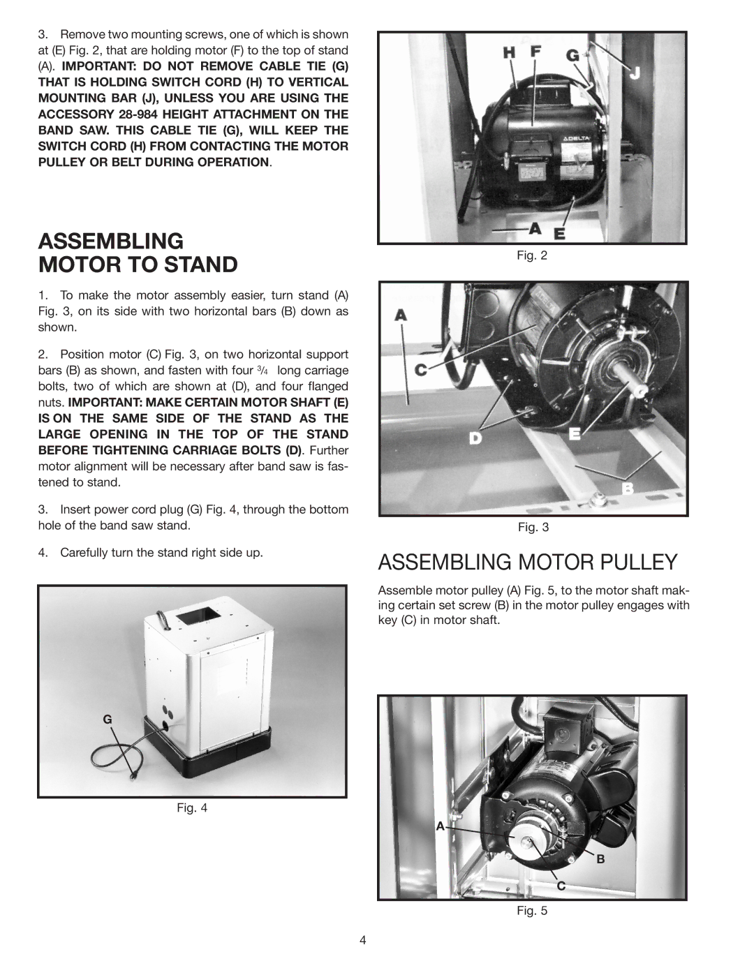
ASSEMBLING MOTOR PULLEY
Assemble motor pulley (A) Fig. 5, to the motor shaft mak- ing certain set screw (B) in the motor pulley engages with key (C) in motor shaft.
A
B
C
Fig. 5
4