ACCESSORY MOULDING CUTTERHEAD
USING MOULDING CUTTERHEAD
Moulding is cutting a shape on the edge or face of the work. Cutting mouldings with a moulding cutterhead is a fast, safe and clean operation.The many different knife shapes available make it possible for the operator to produce almost any kind of mouldings, such as various styles of corner moulds, picture frames, table edges, etc.
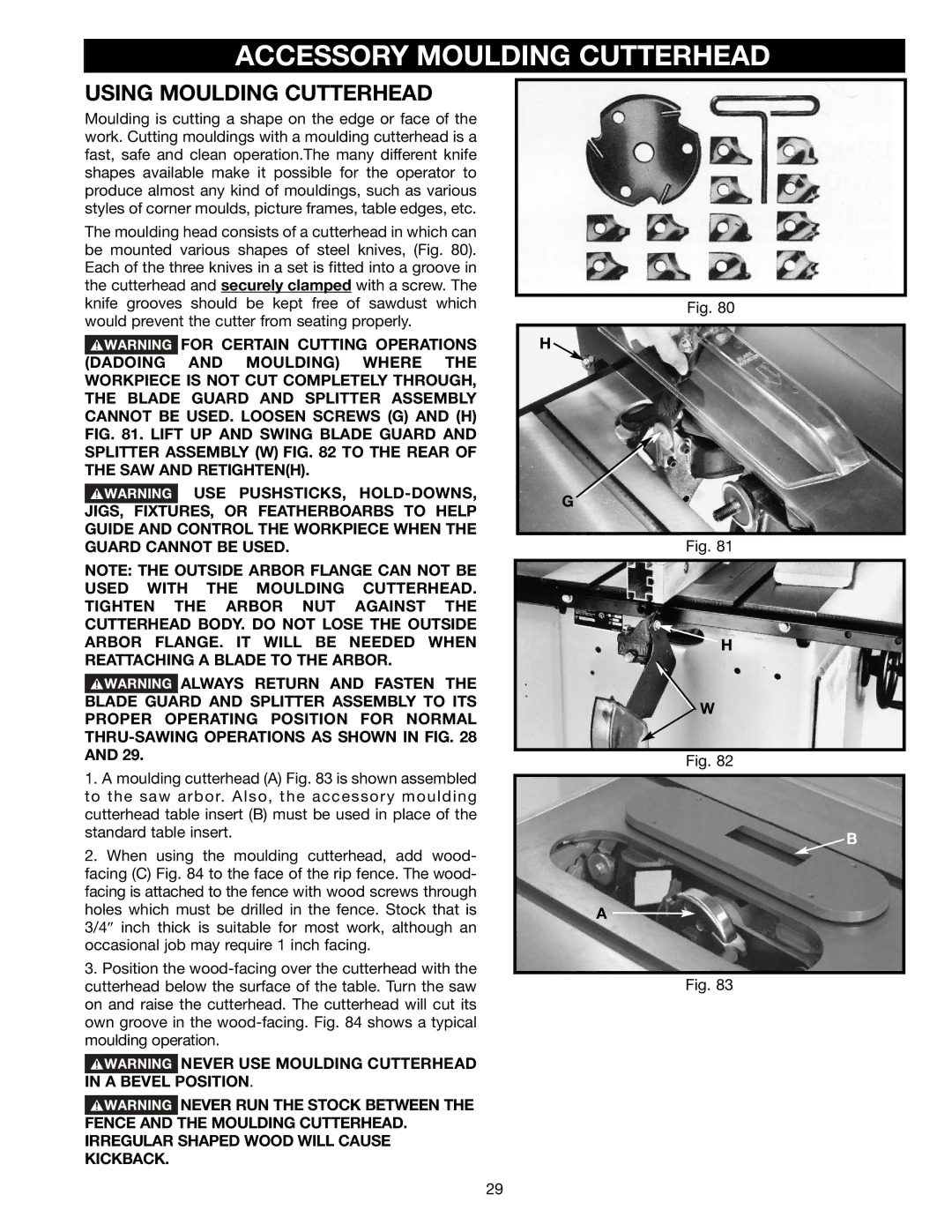
The moulding head consists of a cutterhead in which can be mounted various shapes of steel knives, (Fig. 80). Each of the three knives in a set is fitted into a groove in the cutterhead and securely clamped with a screw. The knife grooves should be kept free of sawdust which would prevent the cutter from seating properly.
![]() FOR CERTAIN CUTTING OPERATIONS (DADOING AND MOULDING) WHERE THE WORKPIECE IS NOT CUT COMPLETELY THROUGH, THE BLADE GUARD AND SPLITTER ASSEMBLY CANNOT BE USED. LOOSEN SCREWS (G) AND (H) FIG. 81. LIFT UP AND SWING BLADE GUARD AND SPLITTER ASSEMBLY (W) FIG. 82 TO THE REAR OF THE SAW AND RETIGHTEN(H).
FOR CERTAIN CUTTING OPERATIONS (DADOING AND MOULDING) WHERE THE WORKPIECE IS NOT CUT COMPLETELY THROUGH, THE BLADE GUARD AND SPLITTER ASSEMBLY CANNOT BE USED. LOOSEN SCREWS (G) AND (H) FIG. 81. LIFT UP AND SWING BLADE GUARD AND SPLITTER ASSEMBLY (W) FIG. 82 TO THE REAR OF THE SAW AND RETIGHTEN(H).
![]() USE PUSHSTICKS,
USE PUSHSTICKS,
NOTE: THE OUTSIDE ARBOR FLANGE CAN NOT BE USED WITH THE MOULDING CUTTERHEAD. TIGHTEN THE ARBOR NUT AGAINST THE CUTTERHEAD BODY. DO NOT LOSE THE OUTSIDE ARBOR FLANGE. IT WILL BE NEEDED WHEN REATTACHING A BLADE TO THE ARBOR.
![]() ALWAYS RETURN AND FASTEN THE BLADE GUARD AND SPLITTER ASSEMBLY TO ITS PROPER OPERATING POSITION FOR NORMAL
ALWAYS RETURN AND FASTEN THE BLADE GUARD AND SPLITTER ASSEMBLY TO ITS PROPER OPERATING POSITION FOR NORMAL
1.A moulding cutterhead (A) Fig. 83 is shown assembled to the saw arbor. Also, the accessory moulding cutterhead table insert (B) must be used in place of the standard table insert.
2.When using the moulding cutterhead, add wood- facing (C) Fig. 84 to the face of the rip fence. The wood- facing is attached to the fence with wood screws through holes which must be drilled in the fence. Stock that is 3/4″ inch thick is suitable for most work, although an occasional job may require 1 inch facing.
3.Position the
![]() NEVER USE MOULDING CUTTERHEAD IN A BEVEL POSITION.
NEVER USE MOULDING CUTTERHEAD IN A BEVEL POSITION.
![]() NEVER RUN THE STOCK BETWEEN THE FENCE AND THE MOULDING CUTTERHEAD. IRREGULAR SHAPED WOOD WILL CAUSE KICKBACK.
NEVER RUN THE STOCK BETWEEN THE FENCE AND THE MOULDING CUTTERHEAD. IRREGULAR SHAPED WOOD WILL CAUSE KICKBACK.
Fig. 80
H ![]()
G
Fig. 81
H
W
Fig. 82
B
A ![]()
Fig. 83
29