
36-902 specifications
The Delta 36-902 is a powerful and versatile table saw designed for both professional woodworkers and serious DIY enthusiasts. Known for its exceptional precision and robust build quality, this saw has become a staple in workshops around the globe. This article will explore the main features, technologies, and characteristics of the Delta 36-902, highlighting its efficiency and functionality.One of the standout features of the Delta 36-902 is its 15-amp motor, which delivers impressive power for cutting through a wide range of materials, including hardwoods and engineered wood. The motor provides up to 4,800 RPM, allowing for smooth and clean cuts. This is complemented by a heavy-duty cast iron table that measures 27 x 40 inches, providing substantial workspace for larger projects and ensuring stability during use.
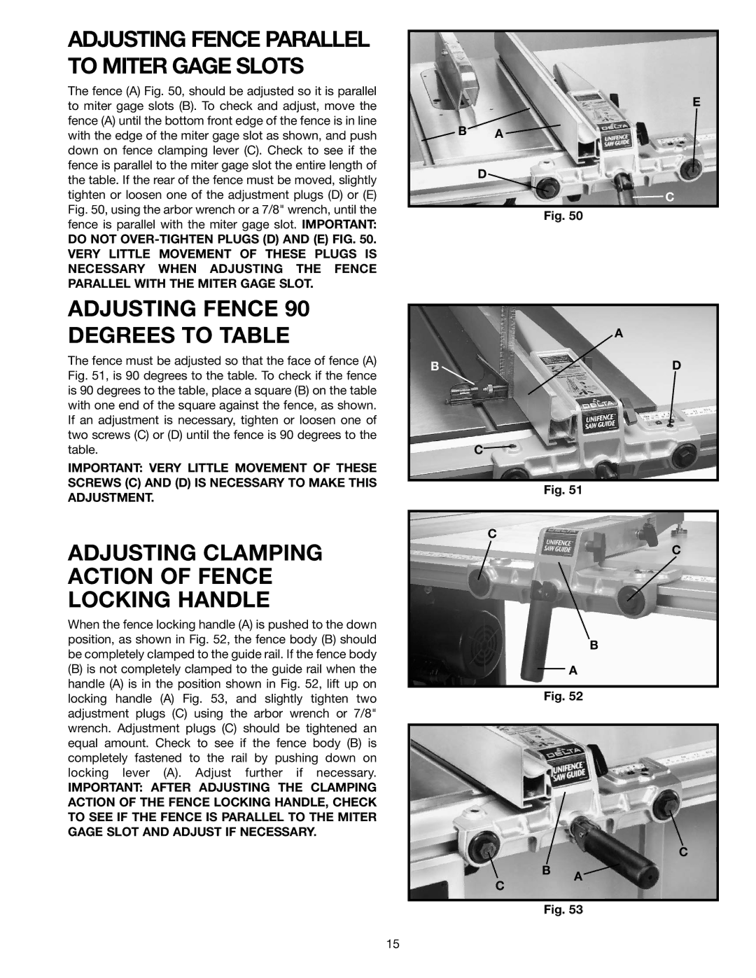
The Delta 36-902 features a patented Unifence system that allows for easy adjustments and precise measurements. The fence can be easily moved, locked, and adjusted, providing unmatched accuracy for rip cuts. Additionally, it features an extensive cutting capacity, allowing for a maximum rip width of 30 inches, making it suitable for larger panels.
Another innovative technology integrated into the Delta 36-902 is its blade raising and lowering mechanism. This easy-to-operate crank allows for quick height adjustments, ensuring users can switch between various cutting depths efficiently. The saw also incorporates a high-quality blade guard system that enhances user safety, minimizing exposure to the blade while maximizing visibility.
The Delta 36-902 is built with user convenience in mind. It includes onboard storage for accessories, such as blades and wrenches, ensuring everything is organized and within easy reach. Additionally, its portability features, including a sturdy wheeled stand, make it easy to move the saw in and out of the workshop, providing versatility for different working environments.
Overall, the Delta 36-902 table saw combines robust construction, advanced technology, and user-friendly design, making it a preferred choice for woodworkers who prioritize precision and efficiency. With its powerful motor, extensive cutting capacity, and safety features, it is well-suited for a variety of woodworking tasks, from intricate joinery to large-scale panel cuts. Whether for professional use or home projects, the Delta 36-902 proves to be a reliable and effective tool.