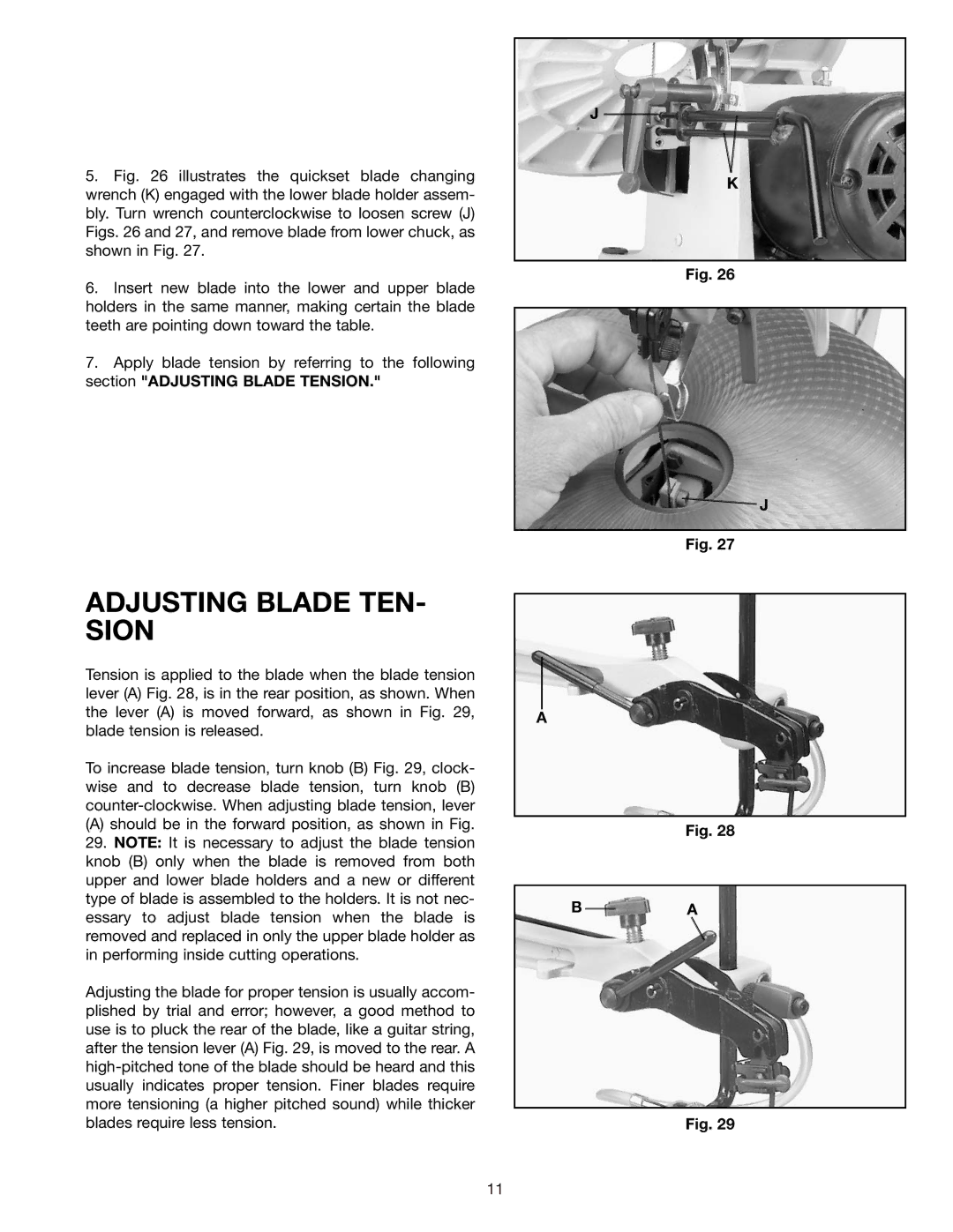
5.Fig. 26 illustrates the quickset blade changing wrench (K) engaged with the lower blade holder assem- bly. Turn wrench counterclockwise to loosen screw (J) Figs. 26 and 27, and remove blade from lower chuck, as shown in Fig. 27.
6.Insert new blade into the lower and upper blade holders in the same manner, making certain the blade teeth are pointing down toward the table.
7.Apply blade tension by referring to the following section "ADJUSTING BLADE TENSION."
J
K
Fig. 26
![]() J
J
Fig. 27
ADJUSTING BLADE TEN- SION
Tension is applied to the blade when the blade tension lever (A) Fig. 28, is in the rear position, as shown. When the lever (A) is moved forward, as shown in Fig. 29, blade tension is released.
To increase blade tension, turn knob (B) Fig. 29, clock- wise and to decrease blade tension, turn knob (B)
(A)should be in the forward position, as shown in Fig. 29. NOTE: It is necessary to adjust the blade tension knob (B) only when the blade is removed from both upper and lower blade holders and a new or different type of blade is assembled to the holders. It is not nec- essary to adjust blade tension when the blade is removed and replaced in only the upper blade holder as in performing inside cutting operations.
Adjusting the blade for proper tension is usually accom- plished by trial and error; however, a good method to use is to pluck the rear of the blade, like a guitar string, after the tension lever (A) Fig. 29, is moved to the rear. A
A
Fig. 28
BA
Fig. 29
11