ASSEMBLY
![]() WARNING: FOR YOUR OWN SAFETY, DO NOT CONNECT THE MACHINE TO THE POWER SOURCE UNTIL THE MACHINE IS COMPLETELY ASSEMBLED AND YOU READ AND UNDERSTAND THE ENTIRE INSTRUCTION MANUAL.
WARNING: FOR YOUR OWN SAFETY, DO NOT CONNECT THE MACHINE TO THE POWER SOURCE UNTIL THE MACHINE IS COMPLETELY ASSEMBLED AND YOU READ AND UNDERSTAND THE ENTIRE INSTRUCTION MANUAL.
ASSEMBLING
ACCESSORY STAND
If you purchased the accessory stand for use with your Router/Shaper, the stand must be assembled as follows:
1.Remove the rubber feet from the bottom of the Router/Shaper.
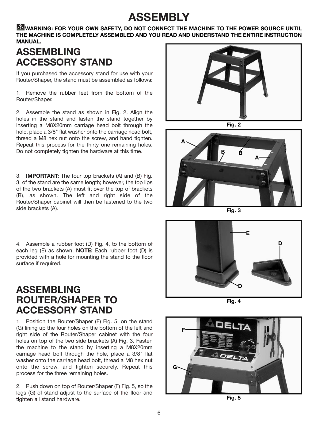
2.Assemble the stand as shown in Fig. 2. Align the holes in the stand and fasten the stand together by inserting a M8X20mm carriage head bolt through the hole, place a 3/8" flat washer onto the carriage head bolt, thread a M8 hex nut onto the screw, and hand tighten. Repeat this process for the thirty one remaining holes. Do not completely tighten the hardware at this time.
3.IMPORTANT: The four top brackets (A) and (B) Fig. 3, of the stand are the same length; however, the top lips of the two brackets (A) must fit over the top of brackets (B), as shown. The left and right side of the Router/Shaper cabinet will then be fastened to the two side brackets (A).
4.Assemble a rubber foot (D) Fig. 4, to the bottom of each leg (E) as shown. NOTE: Each rubber foot (D) is provided with a hole for mounting the stand to the floor surface if required.
ASSEMBLING
ROUTER/SHAPER TO
ACCESSORY STAND
1.Position the Router/Shaper (F) Fig. 5, on the stand
(G) lining up the four holes on the bottom of the left and right side of the Router/Shaper cabinet with the four holes on top of the two side brackets (A) Fig. 3. Fasten the machine to the stand by inserting a M8X20mm carriage head bolt through the hole, place a 3/8" flat washer onto the carriage head bolt, thread a M8 hex nut onto the screw, and tighten securely. Repeat this process for the three remaining holes.
2.Push down on top of Router/Shaper (F) Fig. 5, so the legs (G) of stand adjust to the surface of the floor and tighten all stand hardware.
Fig. 2
A ![]()
B B
A
Fig. 3
E
D
D
Fig. 4
F
G![]()
Fig. 5
6
