ALTERNATE SET-UP
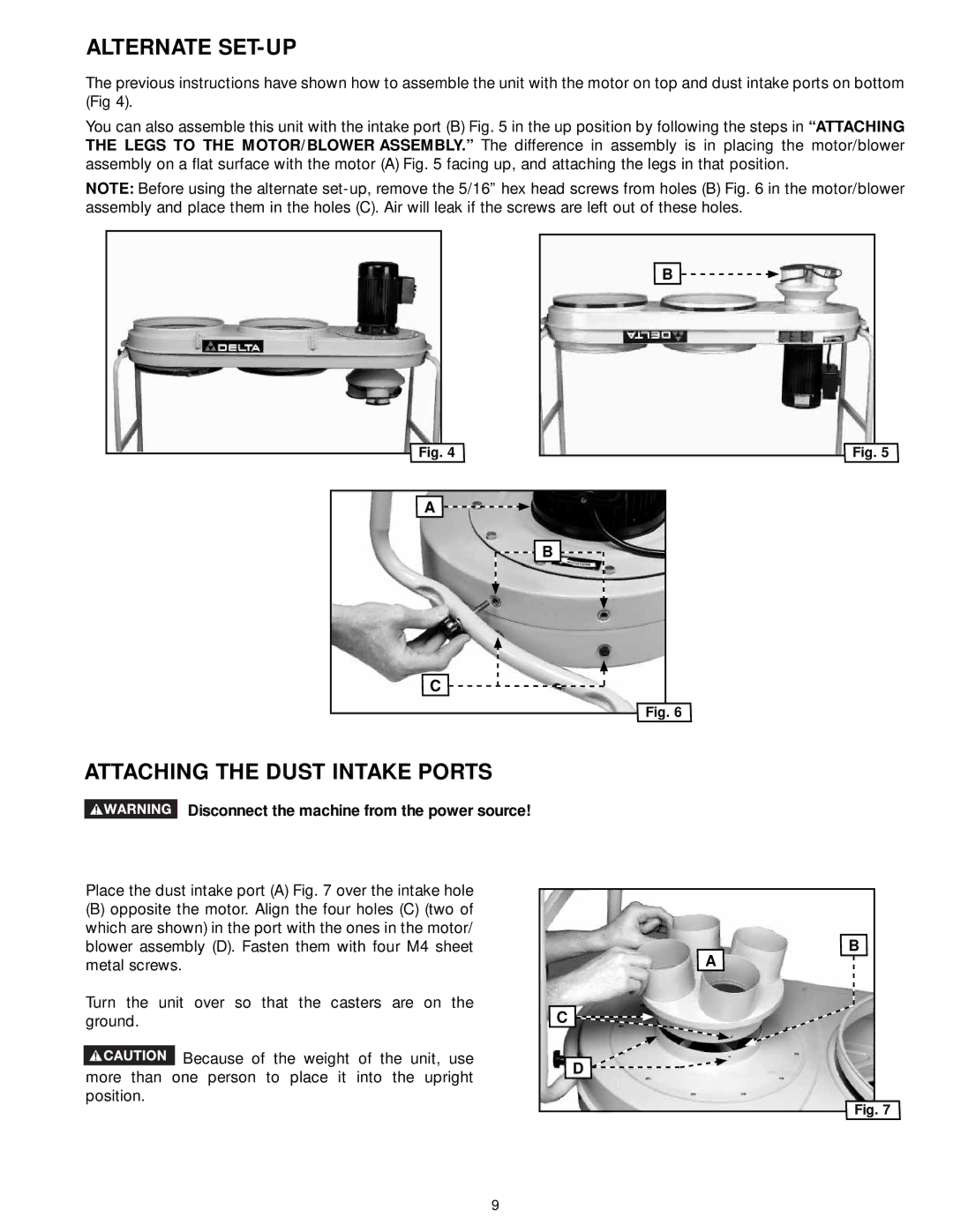
The previous instructions have shown how to assemble the unit with the motor on top and dust intake ports on bottom (Fig 4).
You can also assemble this unit with the intake port (B) Fig. 5 in the up position by following the steps in “ATTACHING THE LEGS TO THE MOTOR/BLOWER ASSEMBLY.” The difference in assembly is in placing the motor/blower assembly on a flat surface with the motor (A) Fig. 5 facing up, and attaching the legs in that position.
NOTE: Before using the alternate
B
Fig. 4
A
Fig. 5
B
C ![]()
Fig. 6
ATTACHING THE DUST INTAKE PORTS
Disconnect the machine from the power source!
Place the dust intake port (A) Fig. 7 over the intake hole
(B)opposite the motor. Align the four holes (C) (two of which are shown) in the port with the ones in the motor/ blower assembly (D). Fasten them with four M4 sheet metal screws.
Turn the unit over so that the casters are on the ground.
Because of the weight of the unit, use more than one person to place it into the upright position.
B |
A |
C |
D |
Fig. 7 |
9