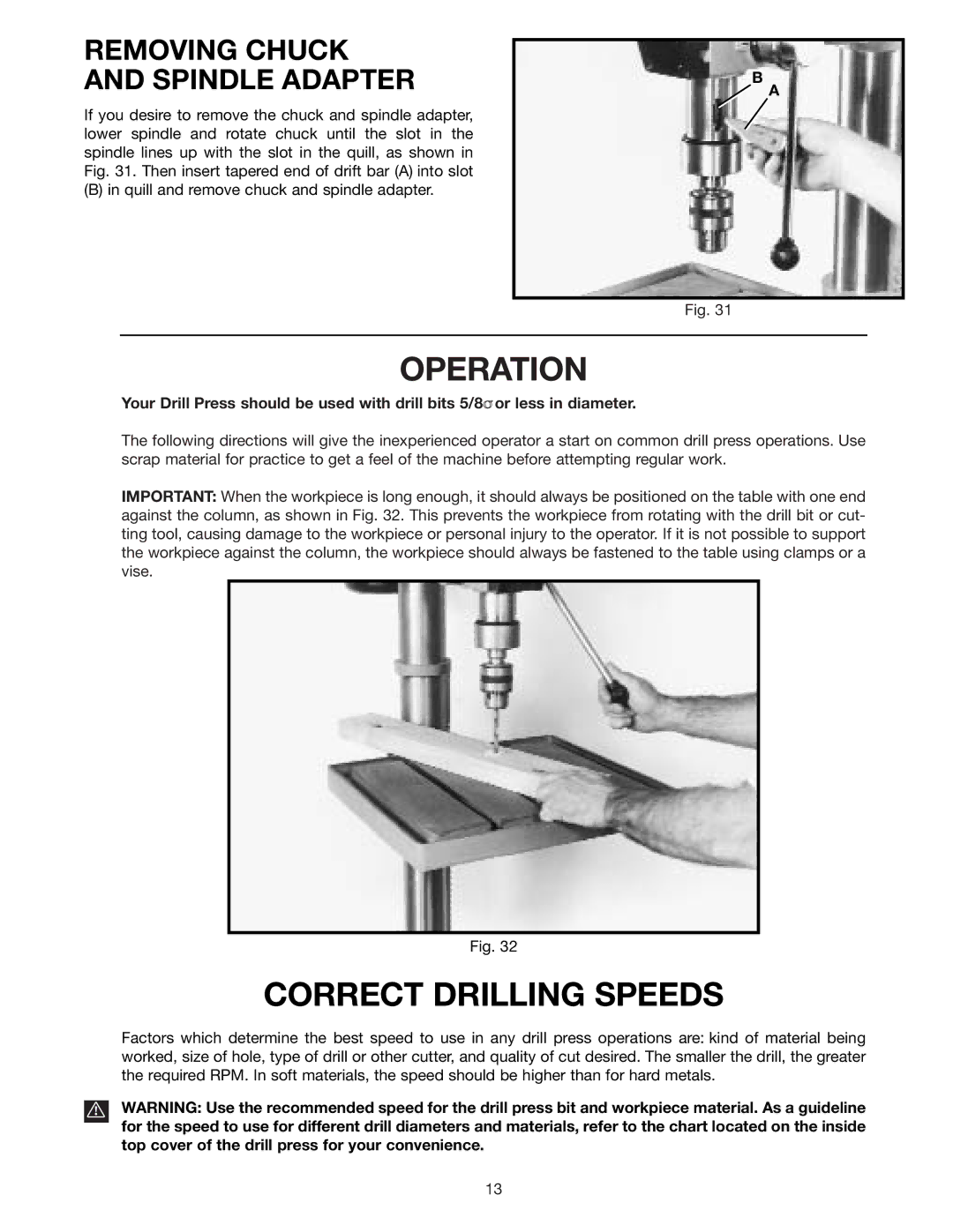
REMOVING CHUCK AND SPINDLE ADAPTER
If you desire to remove the chuck and spindle adapter, lower spindle and rotate chuck until the slot in the spindle lines up with the slot in the quill, as shown in Fig. 31. Then insert tapered end of drift bar (A) into slot
(B) in quill and remove chuck and spindle adapter.
B
A
Fig. 31
OPERATION
Your Drill Press should be used with drill bits 5/8 or less in diameter.
The following directions will give the inexperienced operator a start on common drill press operations. Use scrap material for practice to get a feel of the machine before attempting regular work.
IMPORTANT: When the workpiece is long enough, it should always be positioned on the table with one end against the column, as shown in Fig. 32. This prevents the workpiece from rotating with the drill bit or cut- ting tool, causing damage to the workpiece or personal injury to the operator. If it is not possible to support the workpiece against the column, the workpiece should always be fastened to the table using clamps or a vise.
Fig. 32
CORRECT DRILLING SPEEDS
Factors which determine the best speed to use in any drill press operations are: kind of material being worked, size of hole, type of drill or other cutter, and quality of cut desired. The smaller the drill, the greater the required RPM. In soft materials, the speed should be higher than for hard metals.
WARNING: Use the recommended speed for the drill press bit and workpiece material. As a guideline for the speed to use for different drill diameters and materials, refer to the chart located on the inside top cover of the drill press for your convenience.
13