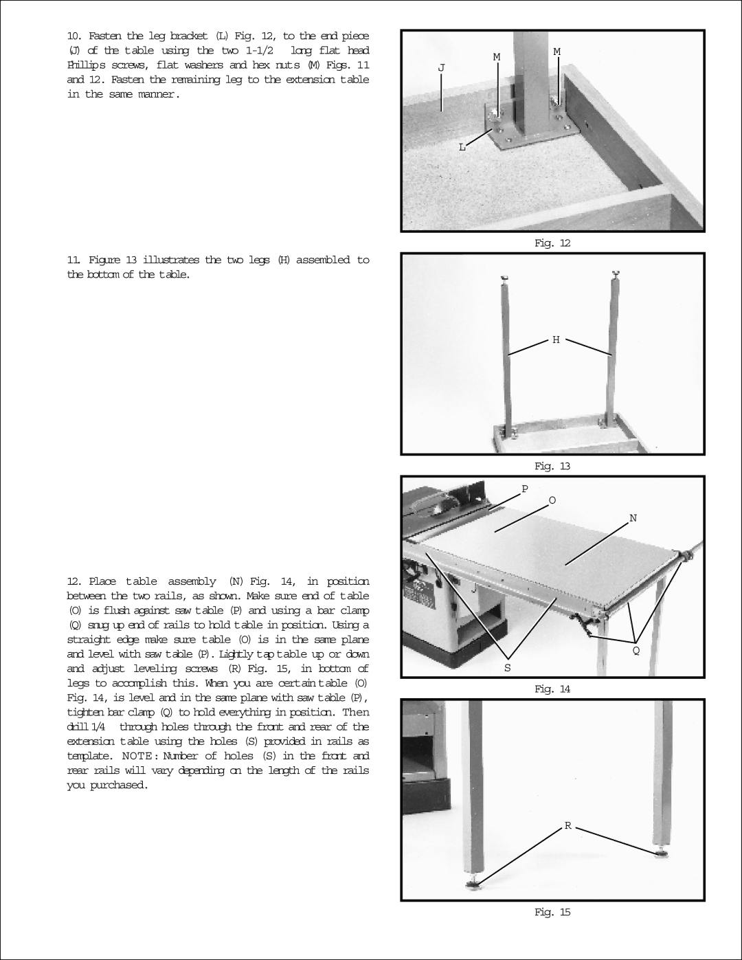
10. Fasten the leg bracket (L) Fig. 12, to the end piece
(J) of the table using the two
11.Figure 13 illustrates the two legs (H) assembled to the bottom of the table.
M M
J
L![]()
Fig. 12
H
12.Place table assembly (N) Fig. 14, in position between the two rails, as shown. Make sure end of table
(O) is flush against saw table (P) and using a bar clamp
(Q) snug up end of rails to hold table in position. Using a straight edge make sure table (O) is in the same plane and level with saw table (P). Lightly taptable up or down and adjust leveling screws (R) Fig. 15, in bottom of legs to accomplish this. When you are certain table (O) Fig. 14, is level and in the same plane with saw table (P), tighten bar clamp (Q) to hold everything in position. Then drill1/4 through holes through the front and rear of the extension table using the holes (S) provided in rails as template. NOTE: Number of holes (S) in the front and rear rails will vary depending on the length of the rails you purchased.
Fig. 13
P |
O |
N |
Q |
S |
Fig. 14
R
Fig. 15