•Check spray pattern from nozzles to be sure there is no clogging. Remove drift eliminators for nozzle inspection, then return to proper position.
•Start up fan motor and check amperage and voltage against motor nameplate data.
•The standard
•After 24 hours of operation:
Check spray nozzles for clogging.
Check tower sump water level.
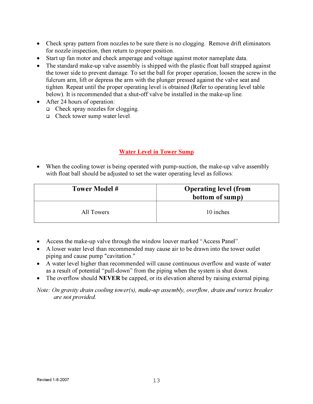
Water Level in Tower Sump
•When the cooling tower is being operated with
Tower Model # | Operating level (from |
| bottom of sump) |
All Towers | 10 inches |
|
|
•Access the
•A lower water level than recommended may cause air to be drawn into the tower outlet piping and cause pump "cavitation."
•A water level higher than recommended will cause continuous overflow and waste of water as a result of potential
•The overflow should NEVER be capped, or its elevation altered by raising external piping.
Note: On gravity drain cooling tower(s),
Revised | 13 |