CUTTERHEAD GUARD
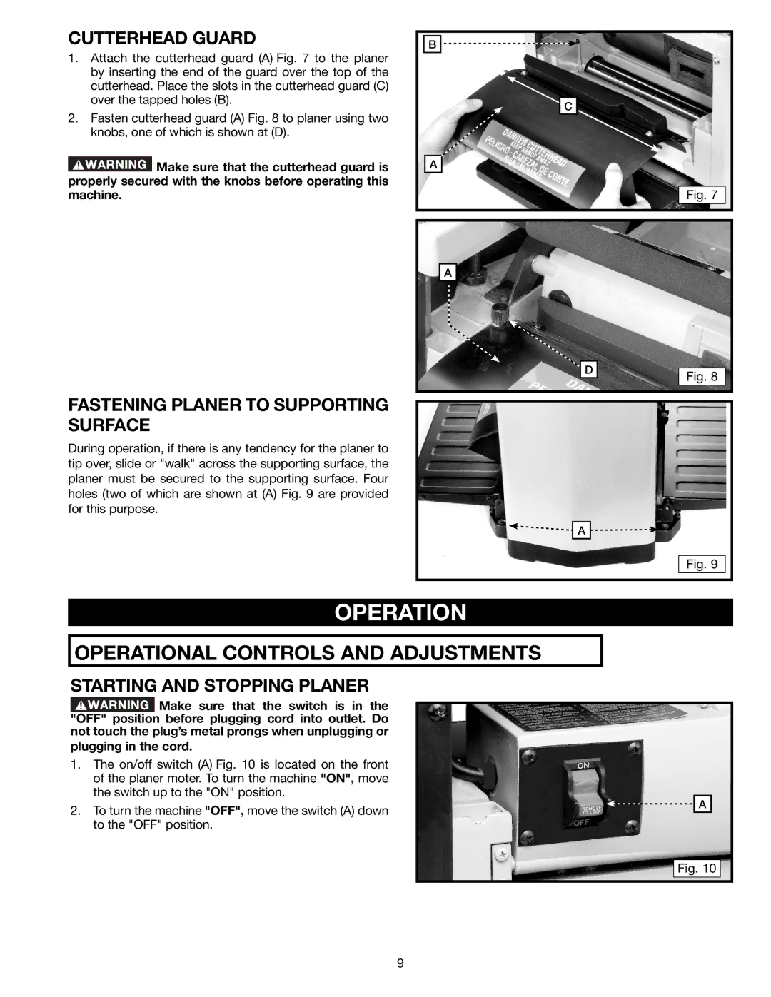
1.Attach the cutterhead guard (A) Fig. 7 to the planer by inserting the end of the guard over the top of the cutterhead. Place the slots in the cutterhead guard (C) over the tapped holes (B).
2.Fasten cutterhead guard (A) Fig. 8 to planer using two knobs, one of which is shown at (D).
![]() Make sure that the cutterhead guard is properly secured with the knobs before operating this machine.
Make sure that the cutterhead guard is properly secured with the knobs before operating this machine.
B |
C |
A |
Fig. 7 |
FASTENING PLANER TO SUPPORTING SURFACE
During operation, if there is any tendency for the planer to tip over, slide or "walk" across the supporting surface, the planer must be secured to the supporting surface. Four holes (two of which are shown at (A) Fig. 9 are provided for this purpose.
A
D
Fig. 8
![]()
![]() A
A ![]()
![]()
Fig. 9
OPERATION
OPERATIONAL CONTROLS AND ADJUSTMENTS
STARTING AND STOPPING PLANER
![]() Make sure that the switch is in the "OFF" position before plugging cord into outlet. Do not touch the plug’s metal prongs when unplugging or
Make sure that the switch is in the "OFF" position before plugging cord into outlet. Do not touch the plug’s metal prongs when unplugging or
plugging in the cord.
1.The on/off switch (A) Fig. 10 is located on the front of the planer moter. To turn the machine "ON", move the switch up to the "ON" position.
2.To turn the machine "OFF", move the switch (A) down to the "OFF" position.
![]()
![]() A
A
C
Fig. 10
9