LOCKING SWITCH IN THE "OFF" POSITION
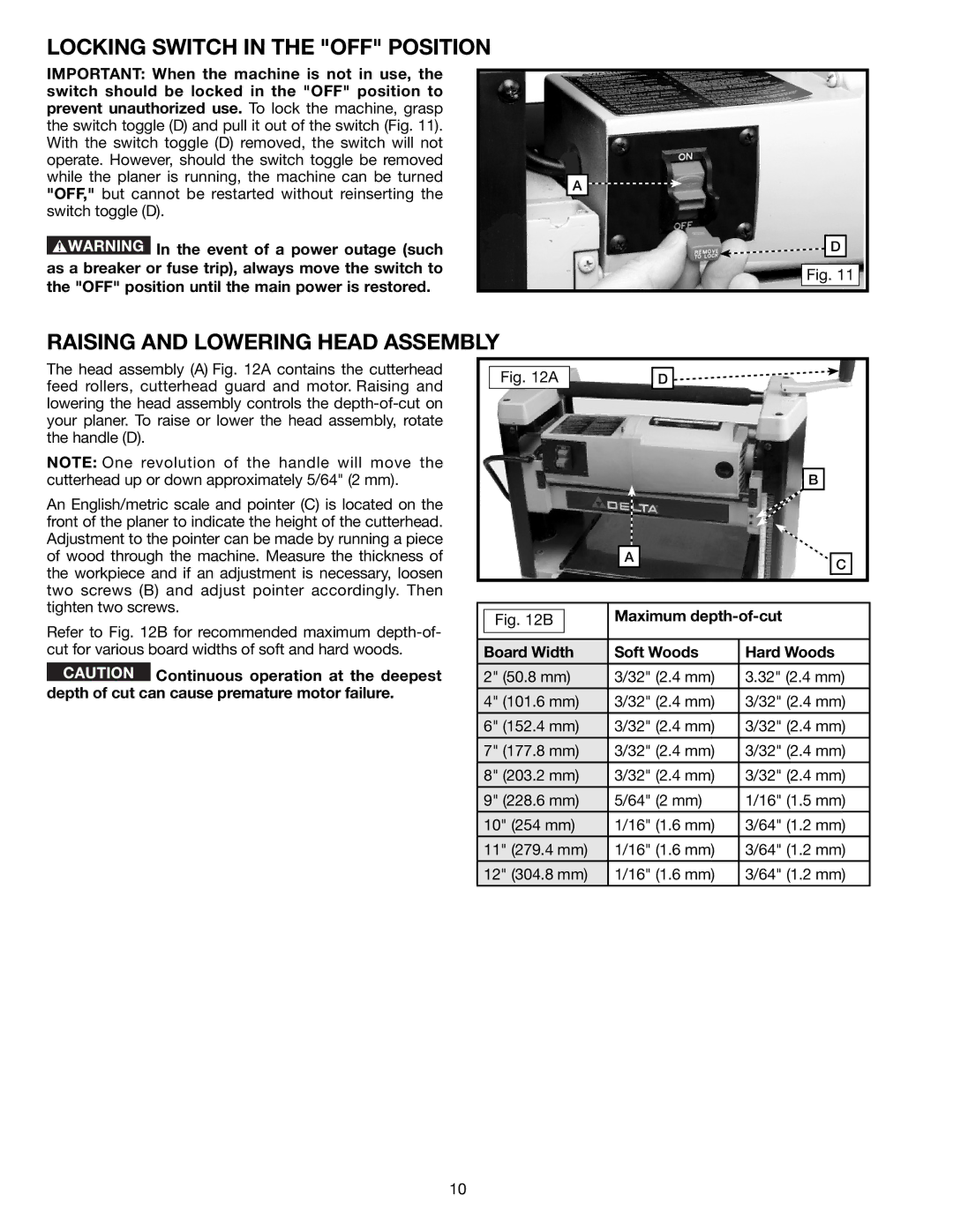
IMPORTANT: When the machine is not in use, the switch should be locked in the "OFF" position to prevent unauthorized use. To lock the machine, grasp the switch toggle (D) and pull it out of the switch (Fig. 11). With the switch toggle (D) removed, the switch will not operate. However, should the switch toggle be removed while the planer is running, the machine can be turned "OFF," but cannot be restarted without reinserting the switch toggle (D).
![]() In the event of a power outage (such as a breaker or fuse trip), always move the switch to the "OFF" position until the main power is restored.
In the event of a power outage (such as a breaker or fuse trip), always move the switch to the "OFF" position until the main power is restored.
A
![]() D
D
Fig. 11
RAISING AND LOWERING HEAD ASSEMBLY
The head assembly (A) Fig. 12A contains the cutterhead feed rollers, cutterhead guard and motor. Raising and lowering the head assembly controls the
NOTE: One revolution of the handle will move the cutterhead up or down approximately 5/64" (2 mm).
An English/metric scale and pointer (C) is located on the front of the planer to indicate the height of the cutterhead. Adjustment to the pointer can be made by running a piece of wood through the machine. Measure the thickness of the workpiece and if an adjustment is necessary, loosen two screws (B) and adjust pointer accordingly. Then tighten two screws.
Refer to Fig. 12B for recommended maximum
![]() Continuous operation at the deepest depth of cut can cause premature motor failure.
Continuous operation at the deepest depth of cut can cause premature motor failure.
Fig. 12A |
| D |
|
| B |
| A | C |
|
|
|
|
| Maximum | |
| Fig. 12B |
| ||
|
|
|
|
|
|
|
|
|
|
| Board Width | Soft Woods | Hard Woods | |
|
|
|
|
|
| 2" (50.8 mm) | 3/32" (2.4 mm) | 3.32" (2.4 mm) | |
|
|
|
|
|
| 4" (101.6 mm) | 3/32" (2.4 mm) | 3/32" (2.4 mm) | |
| 6" (152.4 mm) | 3/32" (2.4 mm) | 3/32" (2.4 mm) | |
|
|
|
|
|
| 7" (177.8 mm) | 3/32" (2.4 mm) | 3/32" (2.4 mm) | |
|
|
|
|
|
| 8" (203.2 mm) | 3/32" (2.4 mm) | 3/32" (2.4 mm) | |
|
|
|
|
|
| 9" (228.6 mm) | 5/64" (2 mm) | 1/16" (1.5 mm) | |
|
|
|
|
|
| 10" (254 mm) | 1/16" (1.6 mm) | 3/64" (1.2 mm) | |
|
|
|
|
|
| 11" (279.4 mm) | 1/16" (1.6 mm) | 3/64" (1.2 mm) | |
|
|
|
|
|
| 12" (304.8 mm) | 1/16" (1.6 mm) | 3/64" (1.2 mm) | |
|
|
|
|
|
10