LEVELING EXTENSION TABLES
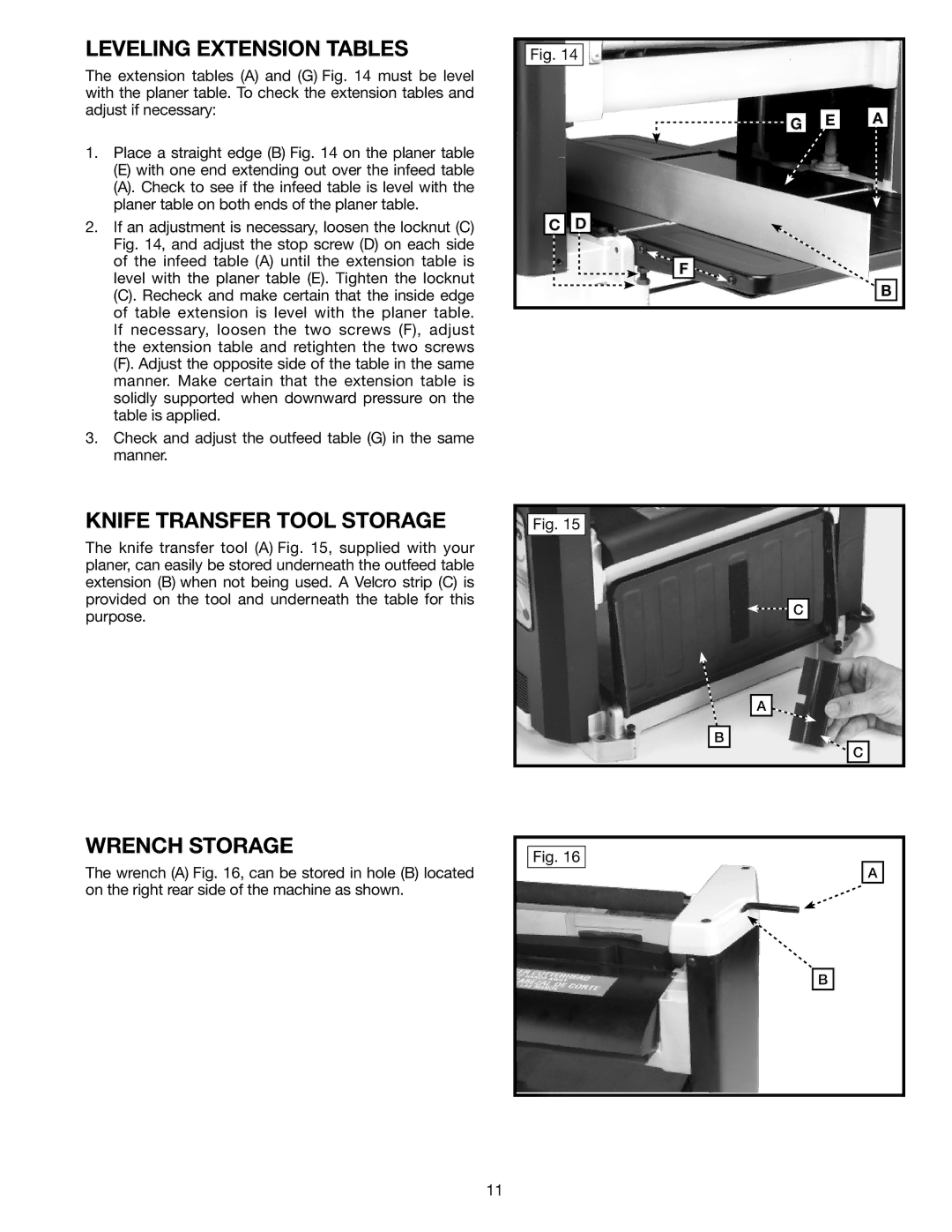
The extension tables (A) and (G) Fig. 14 must be level with the planer table. To check the extension tables and adjust if necessary:
1.Place a straight edge (B) Fig. 14 on the planer table
(E)with one end extending out over the infeed table
(A).Check to see if the infeed table is level with the planer table on both ends of the planer table.
2.If an adjustment is necessary, loosen the locknut (C) Fig. 14, and adjust the stop screw (D) on each side of the infeed table (A) until the extension table is level with the planer table (E). Tighten the locknut
(C).Recheck and make certain that the inside edge of table extension is level with the planer table. If necessary, loosen the two screws (F), adjust the extension table and retighten the two screws
(F).Adjust the opposite side of the table in the same manner. Make certain that the extension table is solidly supported when downward pressure on the table is applied.
3.Check and adjust the outfeed table (G) in the same manner.
Fig. 14 |
|
| |
| G | E | A |
C | D |
|
|
| F |
|
|
|
|
| B |
KNIFE TRANSFER TOOL STORAGE
The knife transfer tool (A) Fig. 15, supplied with your planer, can easily be stored underneath the outfeed table extension (B) when not being used. A Velcro strip (C) is provided on the tool and underneath the table for this purpose.
Fig. 15
![]()
![]() C
C
A
B ![]()
![]()
![]() C
C
WRENCH STORAGE
The wrench (A) Fig. 16, can be stored in hole (B) located on the right rear side of the machine as shown.
11
Fig. 16
A
B
