For DNS12xx series
Vtrim = 0.7 − 0.0667 ⋅ (Vout − 0.7525) V
For example, to program the output voltage of a DNS12 module to 3.3 Vdc, Vtrim is calculated as follows
Vtrim = 0.7 − 0.0667 ⋅ (3.3 − 0.7525) = 0.53 V
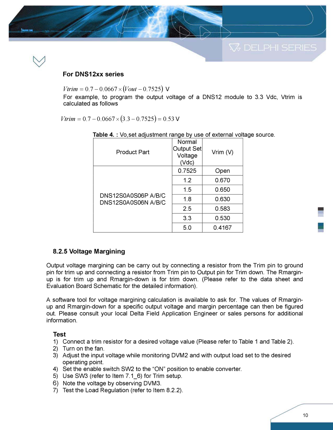
Table 4. : Vo,set adjustment range by use of external voltage source. Normal
Product Part Output Set Vrim (V) Voltage
(Vdc)
0.7525
| 1.2 | 0.670 | |
DNS12S0A0S06P A/B/C | 1.5 | 0.650 | |
|
| ||
1.8 | 0.630 | ||
DNS12S0A0S06N A/B/C | |||
2.5 | 0.583 | ||
| |||
|
|
| |
| 3.3 | 0.530 | |
|
|
| |
| 5.0 | 0.4167 |
8.2.5 Voltage Margining
Output voltage margining can be carry out by connecting a resistor from the Trim pin to ground pin for trim up and connecting a resistor from Trim pin to Output pin for Trim down. The Rmargin- up is for trim up and
A software tool for voltage margining calculation is available to ask for. The values of Rmargin- up and
Test
1)Connect a trim resistor for a desired voltage value (Please refer to Table 1 and Table 2).
2)Turn on the fan.
3)Adjust the input voltage while monitoring DVM2 and with output load set to the desired operating point.
4)Set the enable switch SW2 to the “ON” position to enable converter.
5)Use SW3 (refer to Item 7.1_6) for Trim setup.
6)Note the voltage by observing DVM3.
7)Test the Load Regulation (refer to Item 8.2.2).
10