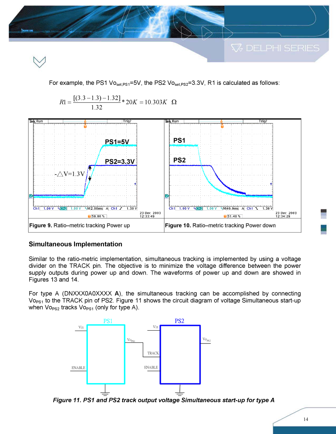
For example, the PS1 Voset,PS1=5V, the PS2 Voset,PS2=3.3V, R1 is calculated as follows:
R1 = | [(3.3 − 1.3) − 1.32] | * 20K = 10.303K Ω | |
1.32 | |||
|
|
PS1=5V
PS2=3.3V
PS1
PS2
Figure 9. Ratio–metric tracking Power up
Figure 10. Ratio–metric tracking Power down
Simultaneous Implementation
Similar to the
For type A (DNXXX0A0XXXX A), the simultaneous tracking can be accomplished by connecting VoPS1 to the TRACK pin of PS2. Figure 11 shows the circuit diagram of voltage Simultaneous
Vin
PS1PS2
Vin
VoPS1
VoPS2
TRACK
ENABLE
ENABLE
Figure 11. PS1 and PS2 track output voltage Simultaneous start-up for type A
14
