Output Voltage Adjustment (TRIM)
To increase or decrease the output voltage set point, the modules may be connected with an external resistor between the TRIM pin and either the Vo+ or Vo
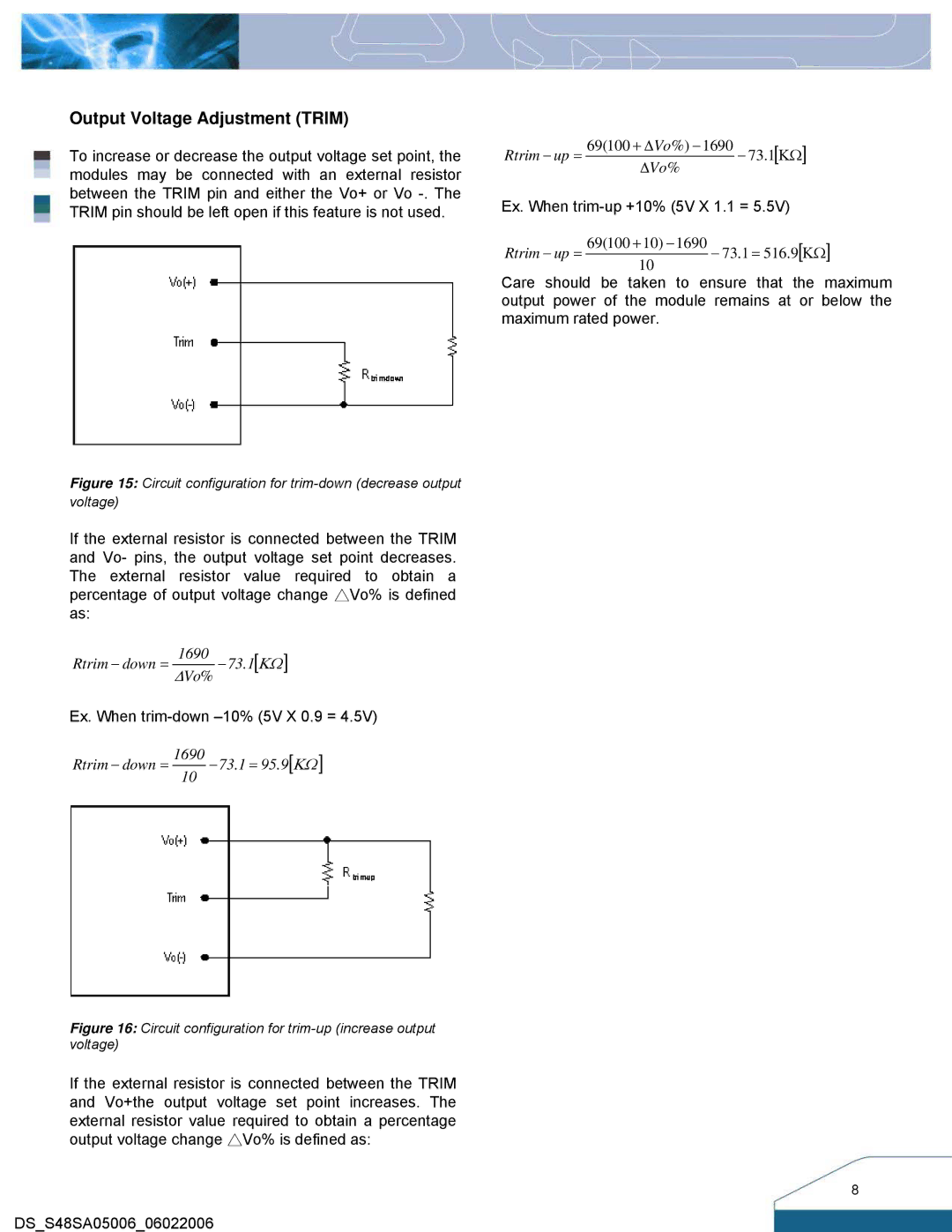
Figure 15: Circuit configuration for trim-down (decrease output voltage)
If the external resistor is connected between the TRIM and Vo- pins, the output voltage set point decreases. The external resistor value required to obtain a percentage of output voltage change △Vo% is defined as:
Rtrim − down = ∆1690Vo% −73.1[ΚΩ ]
Ex. When
Rtrim − down = 169010 −73.1 = 95.9[ΚΩ ]
Figure 16: Circuit configuration for trim-up (increase output voltage)
If the external resistor is connected between the TRIM and Vo+the output voltage set point increases. The external resistor value required to obtain a percentage output voltage change △Vo% is defined as:
DS_S48SA05006_06022006
Rtrim − up = | 69(100 + ∆Vo%) −1690 | − 73.1[ΚΩ] | |
∆Vo% | |||
|
|
Ex. When
Rtrim − up = 69(100 +10) −1690 − 73.1 = 516.9[ΚΩ] 10
Care should be taken to ensure that the maximum output power of the module remains at or below the maximum rated power.
8