Using the BIOS Setup Utility
PCI System Configuration
PCI System Configuration
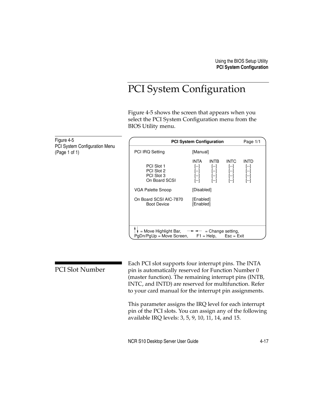
Figure 4-5 shows the screen that appears when you select the PCI System Configuration menu from the BIOS Utility menu.
Figure
PCI System Configuration Menu (Page 1 of 1)
PCI System Configuration |
|
| Page 1/1 | |||||
|
|
|
|
|
|
|
| |
PCI IRQ Setting | [Manual] |
|
|
|
|
|
| |
| INTA | INTB | INTC | INTD | ||||
PCI Slot 1 | ] | ] | [ | [ | ||||
PCI Slot 2 | ] | ] | [ | [ | ||||
PCI Slot 3 | ] | ] | [ | [ | ||||
On Board SCSI | ] | ] | [ | [ | ||||
VGA Palette Snoop | [Disabled] |
|
|
|
|
| ||
On Board SCSI | [Enabled] |
|
|
|
|
| ||
Boot Device | [Enabled] |
|
|
|
|
| ||
| = Move Highlight Bar, |
|
|
| = Change setting, | |
|
|
|
| |||
PgDn/PgUp = Move Screen, | F1 = Help, | Esc = Exit | ||||
|
|
|
|
|
|
|
| Each PCI slot supports four interrupt pins. The INTA | |
PCI Slot Number | ||
pin is automatically reserved for Function Number 0 | ||
| (master function). The remaining interrupt pins (INTB, | |
| INTC, and INTD) are reserved for multifunction. Refer | |
| to your card manual for the interrupt pin assignments. | |
| This parameter assigns the IRQ level for each interrupt | |
| pin of the PCI slots. You can assign any of the following | |
| available IRQ levels: 3, 5, 9, 10, 11, 14, and 15. |
NCR S10 Desktop Server User Guide |