Installing the System
Major Components
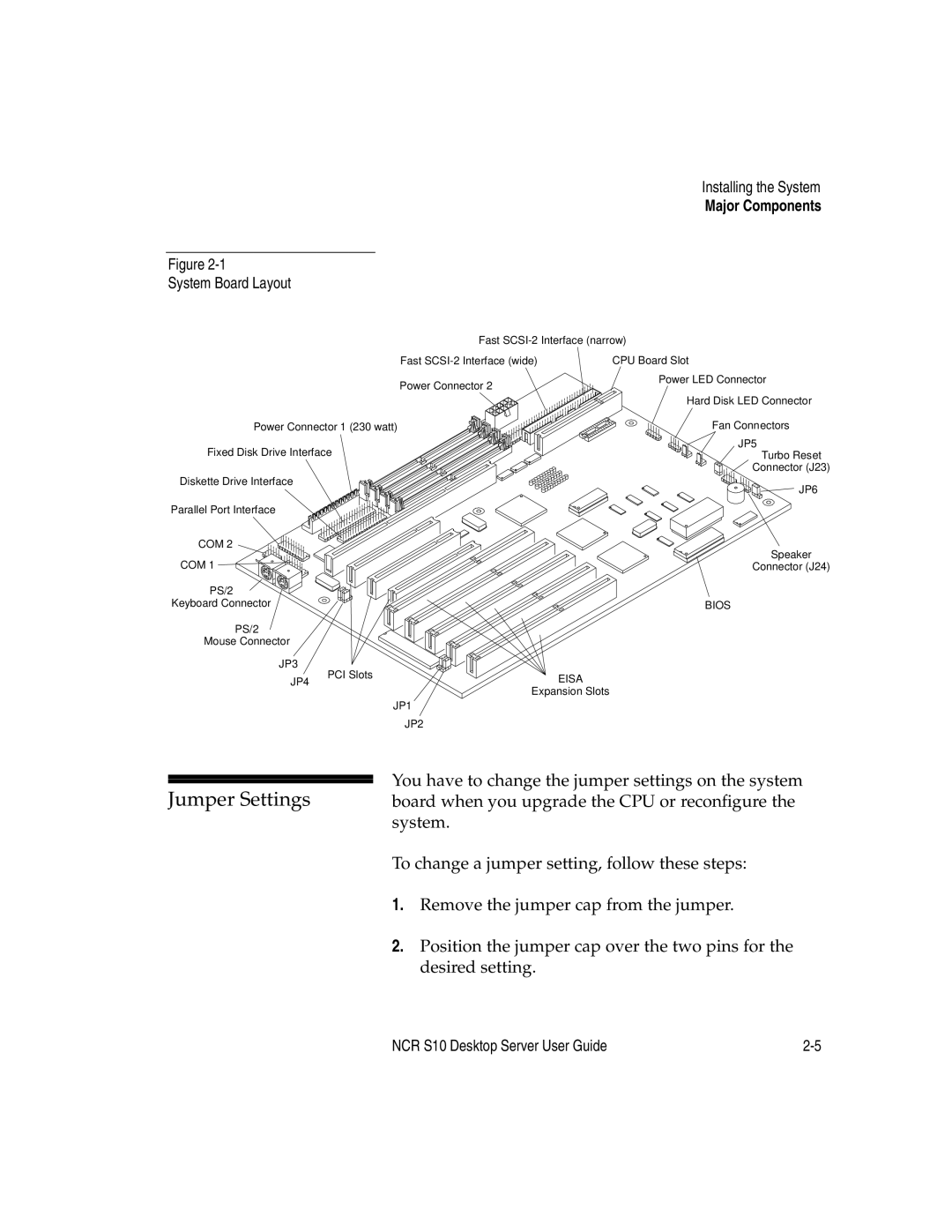
Figure
System Board Layout
Fast | Interface (narrow) |
Fast | CPU Board Slot |
Power Connector 2
Power Connector 1 (230 watt)
Fixed Disk Drive Interface
Diskette Drive Interface
Parallel Port Interface
COM 2
COM 1
PS/2
Keyboard Connector
PS/2
Mouse Connector
JP3 | PCI Slots |
| |
JP4 | EISA | ||
| |||
|
| Expansion Slots | |
|
| JP1 | |
|
| JP2 |
Power LED Connector
Hard Disk LED Connector
Fan Connectors
JP5
Turbo Reset
Connector (J23)
JP6
Speaker
Connector (J24)
BIOS
| You have to change the jumper settings on the system | ||
Jumper Settings | |||
board when you upgrade the CPU or reconfigure the | |||
| system. | ||
| To change a jumper setting, follow these steps: | ||
| 1. | Remove the jumper cap from the jumper. | |
| 2. | Position the jumper cap over the two pins for the | |
|
| desired setting. | |
NCR S10 Desktop Server User Guide |