FEATURES DESCRIPTIONS
Over-Current Protection
The modules include an internal output
The modules will try to restart after shutdown. If the overload condition still exists, the module will shut down again. This restart trial will continue until the overload condition is corrected.
Over-Voltage Protection
The modules include an internal output
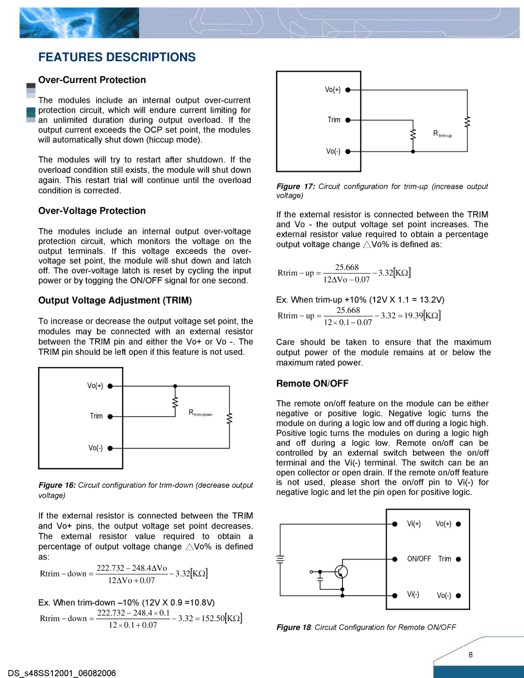
Output Voltage Adjustment (TRIM)
To increase or decrease the output voltage set point, the modules may be connected with an external resistor between the TRIM pin and either the Vo+ or Vo
Vo(+) |
|
Trim | |
| |
|
Figure 16: Circuit configuration for trim-down (decrease output voltage)
If the external resistor is connected between the TRIM and Vo+ pins, the output voltage set point decreases. The external resistor value required to obtain a percentage of output voltage change △Vo% is defined as:
Rtrim − down = 222.732 − 248.4∆Vo − 3.32[ΚΩ] 12∆Vo + 0.07
Ex. When
Rtrim − down = 222.732 − 248.4 × 0.1 − 3.32 = 152.50[ΚΩ] 12 × 0.1 + 0.07
Vo(+) |
Trim |
R |
Figure 17: Circuit configuration for trim-up (increase output voltage)
If the external resistor is connected between the TRIM and Vo - the output voltage set point increases. The external resistor value required to obtain a percentage output voltage change △Vo% is defined as:
Rtrim − up = | 25.668 | − 3.32[ΚΩ] |
12∆Vo − 0.07 |
Ex. When
Rtrim − up = | 25.668 | − 3.32 = 19.39[ΚΩ] |
12 × 0.1 − 0.07 |
Care should be taken to ensure that the maximum output power of the module remains at or below the maximum rated power.
Remote ON/OFF
The remote on/off feature on the module can be either negative or positive logic. Negative logic turns the module on during a logic low and off during a logic high. Positive logic turns the modules on during a logic high and off during a logic low. Remote on/off can be controlled by an external switch between the on/off terminal and the
Vi(+) | Vo(+) |
ON/OFF | Trim |
Figure 18: Circuit Configuration for Remote ON/OFF
8
DS_s48SS12001_06082006